

So we have carefully thought about the tradeoffs after reading this chapter (where I cut through all the fanboy crap to what really matters), and decided that lithium batteries are the way to go for our offshore voyaging boat.
And we have figured out how much usable battery capacity we need and which charging sources and output power are required to keep up with our usage, as well as whether our system will be 12 or 24 volt, all covered in earlier chapters in this Online Book.
Now what? What gear should we actually buy?
Sure, we can dive into a hundred YouTube videos, but most are by someone who has never, or rarely, been offshore voyaging, and, worse still, many of the presenters could not explain ohms law1 if their lives depended on it—being a great presenter can mask truly stunning ignorance.
Or we can read who knows how many manufacturer web sites, reviews, and/or videos claiming that one particular lithium battery and BMS is best, or best for the money. But how do you decide who is making sense and who is full of shit and/or just trying to make a sale?
And even if we can figure that out, there is no best, there is only best for each of us.
To solve these problems I’m going to explore how each of us can develop our own set of buying criteria so we can cut through the noise to find and buy the best system for us.
The key points that are vital to understand are in the blue (tip) and pink (alert) boxes; that said, it will make more sense if you read the whole article carefully.
Also, I have used photos of various equipment to illustrate the article, but that does not mean I’m specifically endorsing that piece of gear.
What Matters To Us
The absolute number-one thing we need to fix in our minds before we go any further down this lithium-battery system selection road is that the needs of offshore voyaging boats are different and more stringent than pretty much any other usage case except aircraft.
Don’t Look To RVs (Campers)
For example, a system designed for a recreational vehicle (RV) is useless on an offshore voyaging boat because:
- Lithium-battery system load dumps on an RV don’t result in the power steering shutting down (think autopilot), the headlights going dark (think nav lights), and the dials blinking out (think plotter and instruments) in the middle of the highway.
- RVs generally spend a lot more of their time under power and have more room for solar panels in relation to their needs—an RV is more like a motorboat than sailboat.
- Most RV campers spend a lot more time on shore power.
RV lithium-battery systems do not supply mission-critical safety systems (driving), offshore voyaging boat systems do.
It’s also important to understand that RVs are a far bigger market for lithium-battery systems—for example, less than 10% of Wakespeed WS 500 alternator regulators are sold to boat owners—so most of the documentation and suggested configurations we find on the internet do not apply to us.
Compare Against a Benchmark
Next we need to compare against the long-proven solution, a well designed and installed lead-acid based system, and be realistic about what we are taking on when we leave that behind:
- Installing a lithium system that increases the chances of an electrical blackout is bad seamanship.
- If you doubt that, please read this before going further.
- Lithium systems are way, way more complex and intrinsically less reliable and fault tolerant.
If we install a lithium-battery system that’s anything less than done right, we will have taken a huge step backward. The ocean doesn’t give a shit how cool our electrical system is, it only cares about how functional and reliable it is.
Good News, Bad News
The good news is that today we can build a lithium battery-based electrical system that’s makes the offshore voyaging boat grade, and even do that at a relatively reasonable cost.
The bad news is that it’s on us to figure out how to do that in a seamanlike way, since there are no turnkey systems specially designed for our needs.
Actually, there are from Ocean Planet Energy, but even if we decide to buy the whole system from Bruce and his good folks (highly recommended), we still need enough understanding to know what he’s talking about, and to install and maintain the system right; yes, even if we pay someone else to do the actual work.
Why I’m Writing This
But, before I dig into the technology, this article and how it will unfold was, as happens so often, inspired by a member comment:
Right now my hang-up is why LFP communication with the Alternator Regulator is necessary, and I have heard no reasonable technical explanation from anyone yet.
Member, Rick
I have to say that when I first read that I was a little put out. After all, I have written a complete Online Book, much of it explaining just that in detail. If you are too lazy to read it…yada, yada, yada…
But then I realized Rick has a point:
- I need to explain this more simply and in one place, rather than scattered throughout the Book.
- I also need to come up with a solution for those who don’t want to go that far or already have lithium batteries that don’t communicate; often, but not always, called “drop in”.
And then, once we have covered that off, we need a simple, or as simple as it’s possible for me to make it, list of criteria we can use as we buy stuff.
Let’s do that.
Hi John!
Great post and an interesting topic. It will be very interesting to read part two and three.
I am currently in the process of completely rewiring my Sailboat.
In essence this includes everything as my “new-for-me” sailboat from the early 70’s had so many questionable “fixes” and wires “going everywhere and doing nothing” that it it simply felt simpler (and safer) to pull everything out and start from the beginning.
I’m going to follow your earlier recommendation in another post and keep my lead-acid batteries for essential-applications.
I am currently drafting on where and how to connect charging sources. I am currently leaning towards keeping alternator connected to lead acid and everything else to the housebank.
The only three negative points for this solution that I have thought about:
Although I admit I might be overthinking things with point 3 I still think point one and two would be important for a seamanlike system.
Hi Henrik,
I agree, best in those cases to to simply tear everything out and start again.
On your lithium ideas, I agree that keeping a lead acid bank is a good idea, but it does not have to be that complicated. You don’t need to be taking charging sources to both the lead and lithium. As long as we design the lithium system right with a controlling BMS all charge sources should connect to the lithium system.
We have a complete and much simpler solution here including a block diagram, and it includes your point #2: https://www.morganscloud.com/2022/07/03/building-a-seamanlike-lithium-battery-system/https://www.morganscloud.com/2022/07/03/building-a-seamanlike-lithium-battery-system/
No need to overthink it. Just start with the diagram John put in that linked article, calculate your wire sizes and fuse ratings per the ABYC design standards, and install it per the ABYC workmanship standards. That design is the end product of hundreds of hours of analysis by a lot of experienced skippers and clever engineers. It solves all the real issues with as little expense as possible. The only thing I might tweak in it is that, if your lithium BMS supports separate disconnects for load and charge buses rather than requiring a single “disconnect battery entirely” master relay, to separate them accordingly.
And yes, sometimes it is simpler and safer to pull everything out. I’ve found some very interesting damage to some very undersized battery cables when doing this previously.
Hi Matt!
Thanks for the response. I think you are spot on.
Before, I was designing my own system and using some swedish sources and Nigel Calders “Boatowners mechanical and electrical manual” as a guide.
But, Nigel Calders book is a few years old, and european standars seems to be a few years behind regarding lithium, so I have started to go trough the ABYC standards and redesigning my system.
As a big fan of the metric system, I have to say that the ABYC are much better then I feared. Most charts & graphs are “bilingual”, which is of great relief.
My only problem so far is with AIC (ampere interrupting capacity) for overcurrent protection devices.
Most available products for 12-48 volt does not seem to be rated according to this standard. I can pretty much only find products from blue sea products, and honestly, they seem to be a bit overpriced.
Hi Henric,
I sympathize on the cost of BlueSea, particularly in Europe, but still, I would not compromise on AIC. My recommendation is only Class T fuses and also be very careful to make sure you are not buying a counterfeit. According to Rod Collins there are a bunch out there. Bottom line, even an expensive class T is cheap when compared to a boat fire. We already have one member who nearly burned his boat due to installing a counterfeit breaker bought on Amazon.
Well, it took me a couple of days to reply to this message.
I think I went trough at least a few stages of denial.
At first, my response was going to be something along the line off:
But then I started thinking, If I do as you recommend, I do not need to buy:
So if I buy a bigger, better, more functional and seamanlike BMS for 300/400 extra I have actually saved money!
Sometimes new ideas need time to sink in… thanks for the help.
Hi Henrik,
Good thought process, and thanks for sharing it. Ironically, I’m changing too, but the other way, at least a bit. For many, who just don’t want to do it really right, charging the start battery and using a DC/DC is perhaps the way to go. That said, no question that doing it right with the alternator charging the Lithium is optimal. I will write more.
Hi Henrik,
You’ve already gotten many good answers here, so I won’t comment much. Since you’re in Sweden, (I’m Norwegian living in Amsterdam,) you might wanna check out batterybalance.com. Mikael Garton runs it. He’s developed a BMS with a somewhat different philosophy. It’s meant to do all the controls and different stages inside the BMS. Apparently you don’t need to change the alternators or have external regulators. I’m not sure if this is the right philosophy or not, but Mikael is very competent. Seemingly you can choose most options, including using smart external devices.
He developed the BMS because of troubles with several other BMSes, including REC, which repeatedly killed off battery banks. It has an included system that runs a separate backup lead acid bank next to the lithium bank, using the same charge sources, but does not connect them together.
I don’t know enough about this system to evaluate it, but I do think it’s worth evaluating better. I have some experience with REC, and they’re a serious company, of course, but doing setup and maintenance is not a walk in the park, to put it mildly. More like the MS DOS of old days computers… Absolutely not DIY friendly and mainly made for off grid solar systems. Boaters are a very small side market. All is possible to figure out, and there are good forums etc, but just beware:
Even though items communicate with Victron, that doesn’t mean they’re anywhere near the logic and easy to use systems Victron has, in app and online. I haven’t used Wakespeed yet, but that also demands some focus to get it right. I also don’t know how batterybalance is in this respect, but setup is mainly meant to be done via a wired PC or via an optional WiFi. It seems the latter might work on a phone too.
About Victron, they’re the giant in the boat electricity market. Most products they have are the benchmark others try to reach. However, they don’t have everything, and many of their products are somewhat proprietary. They work best with other Victron items. Their BMS is one such. It’s not meant to be used with any other battery than Victron batteries, which have electronics in the box that the BMS needs for its operations. That means it’s not suitable for any other setup. I assume it’s possible to remedy that and still use it, but again, it’s not a walk in the park…
Hi Stein,
I took a look at batterybalance.com and had a scan through the manual.
There is nothing unique or magic about it. Basically it’s a wiggle wire type BMS although it does have some CANbus capability, but he cautions repeatedly about the trouble we can get into with CANbus.
One thing I don’t like about his system is that the charging relay parallels the lithium and lead systems. This will work, but it still violates my basic thinking that two different chemistries should not be put in parallel at any time, except maybe through an isolator, which he does not use, although it could be added, I think. And he uses the starter battery as a backup, which again, I don’t like. That said a smart user could solve both those problems and still use his BMS.
And while his marketing stuff says you don’t have the change the alternator, when we read the manual we find that the alternator needs to be changed and air cooling added.
His system is also twice the price of the Victron Smart BMS 12/200 which will do pretty much everything his will and includes an isolator for the starter battery. But of course the Victron is only meant to work with Victron batteries, so that negates the price advantage.
All that said, I like how he has thought through the whole system and explained it well.
Hi John,
The pro version coming out this spring is supposed to have more capabilities than the main version. I don’t know which one you checked out. Either way, I agree with your thoughts.
About price, his thinking is that the user saves more than the extra cost because this BMS comes with relays and functionality meaning far fewer other investments. If that’s true, I don’t know.
The Victron batteries are great, I’m definitely a Victron fanboy, but even better cells (they don’t use Winston anymore) can be bought for perhaps 20% of the money, if we’re comfortable with making a DIY system. It takes a lot to compensate for that.
Hi John,
Thanks for putting in the work. Well explained. I’ve tried to get the message through as short as possible sometimes. Then without the “why is it like that?” Perhaps useful? About like this:
1. All lithium battery cells must have an electronic device that controls what comes in and goes out, and the state of each cell. A Battery Management System, BMS.
2. All BMS units must have the ability to SHUT OFF the connection between the battery and any consumer or charging source. An offshore sailboat cannot have this RISK.
3. The BMS cuts power for specific REASONS, which are (almost) always caused by things happening outside of the battery.
4. If the BMS can COOPERATE with the systems outside of the battery, it can make them behave in a way that removes the risk of power cutoffs.
The above points are true for all lithium battery types. No exceptions. Pretending that point 4 isn’t essential is caused by either:
A. Lack of knowledge, or
B. Lack of honesty.
Hi Stein,
I agree on almost all of that, except “remove the risk of power cut offs”. My thinking is that with any system as complicated and reliant on as much complicated hardware and software there is always a risk of cut offs. I have also verified that with Al at Wakespeed and Bruce at Ocean Planet.
Therefore I recommend a simple and relatively low cost, fault tolerant, and easy to trouble shoot, lead acid backup system for any offshore voyaging boat: https://www.morganscloud.com/2022/07/03/building-a-seamanlike-lithium-battery-system/
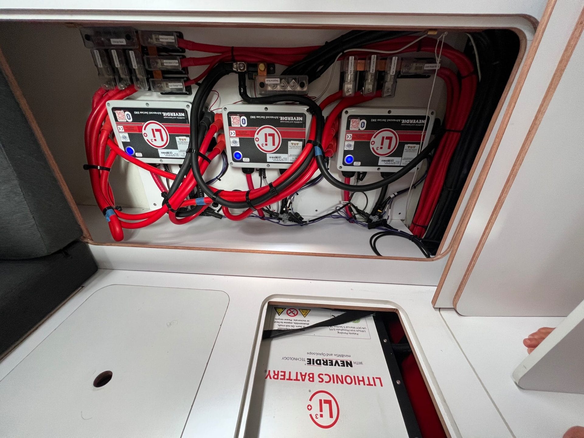
This is further supported by the British classing authorities who insisted on a lead acid serial backup for Andy Schell system despite it being one of the best and most reliable lithium systems available (photo at top of article).
Hi John,
I expected this comment, and I totally agree.
There’s a lot of simplification in my claims, and no explanations. The reason was to punch through the wall of denial many drop-in lithiots 🙂 suffer from. I should probably change point 4 to: “… behave in a way that (almost) removes the risk of power cutoffs.”
Hi Stein,
I expected you to expect me to… Sorry to be such a pain about that, but what I’m realizing is a lot of people put off by doing this right and are desperately searching for justification for doing this easy and wrong (human nature) so that’s why I jump in on that…repeatedly.
Hi John,
You never have to excuse yourself to me about being particular about getting important details right. I think I’m a qualified competitor for the world championship in nitpicking, 🙂 If I were to complain, I’d be a moron. If so, I hope my BMS (Brain Management System) would shut something down. 😀
“The bad news is that it’s on us to figure out how to do that in a seamanlike way, since there are no turnkey systems specially designed for our needs.”
This is actually really good news. This demands that the boat owner fully comprehends the system they are building, so if something does go wrong, they have the knowledge and experience to fix it or circumvent the problem.
On one hand, yes, a well-designed lithium system pretty much requires that the owner-operator be competent to maintain it.
However, there is nothing to stop someone without this knowledge from installing and using a system that is not designed for the voyaging-sailboat situation, or from operating it improperly. Nor is there any easy way for a boat buyer who isn’t already an expert to tell whether a candidate boat’s system is any good. What’s he going to do, trust the surveyor?
I can go on Aliexpress and get a 12V LFP BMS module for $16. Orion’s version is $440. Victron’s is $225. I’m an engineer with years of experience in this stuff, and it takes me a considerable amount of time to parse the documentation and figure out which ones are suitable and which aren’t. It’s all too easy to make wrong calls and break stuff.
I recently talked to a lot of different people selling lithium battery products at a boat show, and would say that perhaps one or two out of a dozen actually seemed to know it well enough to be making recommendations. Most didn’t know who they were sourcing their own components from. Some didn’t even know what chemistry was inside their products. Many of them made up reasonable-sounding, but wrong, responses on the spot rather than admit being stumped.
This series John’s writing is not just a how-to for the boat owner. It’s also a guide to qualifying your suppliers. If they can’t correctly answer every key technical issue raised in John’s articles, you can’t trust them. Maybe you can still buy their stuff, but you need to review its documentation and figure it out yourself.
Hi Matt,
I agree! I’ve done the rounds among lithium dealers, (sounds like drug dealers), for about a decade now. Interestingly, the general level of competence has dropped significantly. It was also not good in the early days. Now, the vast majority of representatives are completely incompetent. That’s including METS, the world’s biggest trade show for marine tech professionals. No basic tech knowledge and no info about their products. Just superficial claims that are usually wrong and almost always misunderstood. The few who have some understanding are used to simplifying the message so that it’s easier to sell. That’s very close to lying.
You’re not exaggerating the difficulties a newbie will encounter when trying to figure out what to do! However, there are also good news. We now have far better sources of information, like here on AAC. We also have far more and better choice of cells and especially better equipment to fit them. It’s way easier to build a good DIY lithium system or a good but less capable drop-in based system today than 10 years ago.
Still, I totally agree that the end user MUST understand the system. Not completely in detail, but a good general understanding of the different parts, what they do and how to keep them happy. Without understanding, there’s no point in having lithium and we’re not competent enough to buy it anyway. Lead acid is better for the person who doesn’t want to understand. However, there’s no such thing as not being able to understand. This is far from rocket science, but there must be an interest.
Hi Stein,
I think that’s a good analysis of the situation.
What I would add is that I’m perfectly OK with, and think none the less of, a person who says screw it, I just want to go sailing, but then, as you say, they should stick with lead acid.
The other issue that we should remember, is that today, and over the last some 30 years, a lot of people have been graduated from our education system without even a basic understanding of physics and this in turn makes learning about something like lithium battery systems brutally hard to do. And of course it makes those people pray to the unscrupulous.
But we must remember (sometimes I forget) that this is not their fault. It’s the fault of an education system that should have let no one graduate high school until they had a BASIC grounding in physics.
There alot of experts in here and a great source of information. Thats so good. But I think it is a problem that you have to be an expert on a subject that to some is complicated. I think it is a problem that there is so much misguided information in the industry. I am speaking from what I have experienced in Denmark. Here there are barely any knowledgable people and alot of ignorant salesmen and most sailors here are DIY. But the stats in Denmark speak for them selves. 5-10 boats burn down on the water every year. And that is most likely pure luck that number is not higher.
So I am glad a site like AAC can cut through the misinformation and the half OK solutions experts recommend people like me that loves to sail and knows a lot of weird shit (also about boats), but clearly needs to read more into Lithium.
In Europe there is alot of good regulation, but on boat electrics the ABYC is the only real standard to lean on and the european manufacuteres don’t always comply with that. The European CE-standard is not precise enough on proper boat electronics.
Hi Martin.
You are right, the standards are much of the problem. While ABYC E13 is better than nothing, it does not even call for BMS process control, only monitoring, which is totally inadequate once we have an alternator in the system. More coming on ways to deal with that, but the bottom line is that this is still in the pioneering stages—I learned a ton from Al yesterday on new stuff they are finding out. Bottom line, even the true experts are still learning.
Rotating electric machines (eg. alternators) and anything including coils (eg. transformers, relays) are inductive. They store energy in their magnetic fields.
So they follow this equation, rather than ohm’s law:
Let’s open a switch and suddenly change the current. I ≠ Io.
Inductance L is a constant (a property of the size and shape of the machine’s windings) so integral(V dt) must become non-zero.
We can have a super fast acting regulator, we can add protection diodes to try to shunt that excess voltage through some safe dump, but we cannot prevent the inductive machine from producing a voltage spike in response to the sudden change in current. It’s part of its fundamental physics.
Hi Mal,
Good question. I can still remember how much trouble I and my class mates back in high school had with this induction, which is what we are dealing with here. We were lucky and had a great physics teacher. Let me see if I can use what he dinned into me, 50 years on!
Matt has provided the math, let’s see if I can build on that without screwing up too badly.
As long as the BMS switches off the alternator either using a control wire connected to the alternator voltage regulator’s “feature” wire, or via CANbus, and then the alternator regulator shuts down the the field coil in the alternator, with the battery still connected, all will be well.
However, if the BMS panics and disconnects the battery without shutting down the alternator first there will be a huge spike no matter what the alternator regulator does. So why, given there are still other loads connected?
This is the nature of inductive generation devices like alternators and wind generators that generate power by moving a coil of wire through a magnetic field, which induces (induction) a voltage difference between the two ends of said coil and therefore current (amps) flow through any loads or batteries connected across the two ends of said coil—there are diodes, but for our purposes here, don’t worry about it.
So if the battery is disconnected from an inductive device when its field coil is still energized and it is supplying a lot of current (amps) to said battery, the magnetic field is still there so we still have a machine that’s producing power. So with with much less current flowing the potential difference (voltage) between the two ends of the coil spikes, typically to over 100 Volts, which does stuff still connected to said alternator no good at all and can also blow the diodes in the alternator.
So why does this not happen when the regulator switches the alternator off properly? Two reasons, I think (reaching a bit here): first off batteries have very low internal resistance so that they, in effect, act as shock absorbers, but more importantly the field coil that the alternator regulator uses to control the alternator has soft iron segments next to it, which only slowly lose their magnetism after the controller removes the control voltage, so the output of the alternator ramps down slowly with no spikes.
Matt: anything I screwed up? Hopefully good old Mike Faraday is not spinning in his grave.
You can read more about inductance here: https://en.wikipedia.org/wiki/Inductance#:~:text=Inductance%20is%20the%20tendency%20of,the%20magnitude%20of%20the%20current.
Alternators generate electricity using this fundamental: Here’s a good explanation of how it all works: https://theengineeringmindset.com/car-alternator-how-alternators-work/ (You can skip down to “How Electricity is Generated With an Alternator”.)
As long as the battery is connected, it’ll absorb any significant transient effects. Batteries are *very* good at being electrical ‘shock absorbers’ or accumulators. A single Group 31 size lead/acid battery can easily source or sink a thousand amps for a couple of seconds with only a 20% or 30% change in terminal voltage.
Alternator regulators work by controlling the current that generates the magnetic field. Increase that current, and you increase the magnetic field strength, thereby increasing the induced voltage in the main windings. At no point does the regulator switch the main windings on or off while the device is active. Changes in the main winding current, provided that a battery is connected, are always smooth and continuous.
The inductive voltage spikes we’re worried about here come from suddenly changing the current in the coil windings of any inductive device, whether static or rotating. (The presence of soft iron gives us more efficient control of the magnetic fields, but you see the same effect even in an air-core coil.) If the alternator is supplying 80 A to the battery and 20 A to all other loads, and you suddenly open the battery switch, that 80 A can’t just stop instantly as it would in a zero-inductance circuit. There’s still a lot of magnetic energy in the coils pushing it along. It’s the electrical equivalent of the “water hammer” you get when a valve closes too quickly: voltage (‘electrical pressure’) jumps up at the point where the circuit was broken, just as water pressure jumps up where the valve was suddenly snapped shut as all the moving water crashes into it.
The remaining still-connected devices can’t absorb that 80 A. They only want 20 A. The energy stored in the inductive device must go somewhere, and what it naturally wants to do is to turn into a high voltage. Indeed, this is precisely how we turn DC power into high voltages for things like taser guns and CRT radar displays. By allowing your BMS to open the battery contactor without first commanding a smooth ramp-down of the charging sources, you are turning your alternator into something resembling a one-shot flyback coil.
Hi Matt,
Good explanation, thanks.
I’m aware about any inductive devise, I just mentioned rotating because we were talking alternators.
Also, I think my point about the soft iron in the stator damping shut down has at least some merit . The reason I say that is I have seen plenty of installations where there are switches in either the field wire or the power wire to the regulator to shut it down and I have never heard of any problems doing this even though I would not do that as standard practice.
Hi Mal,
Glad to hear it made sense. Which batteries have you got that support CAN Bus?
Thanks, Mal, I really appreciate your restraint!
As you go down the CanBuss road be aware that there are at least 5 different protocols for CanBus. Worse still, Al tells me that in all but one case he had to get BMS vendors to reprogram their BMS to work with an alternator at all, CanBus or not. The point being that none of this is standard. My conversation with Al yesterday has convinced me that amateur CAN bus configuration with alternators is very, very difficult, maybe impossible. So you might want to consider a wiggle wire solution if you are still intent on saving those batteries. More coming.
Finally some actual knowledge and facts explained for anyone to understand. Thank you. I think this series is geared towards not an actual understanding, but only enough to keep people from not making big expensive mistakes with off the shelf gear. When I see things like, “two different chemistries should not be put in parallel at any time”, the author and target audience are not trying to be informed. I have a lot of offshore time and a DIY LFP system on my cruising boat that is now 4 years old. The system greatly benefits from having two chemistries in parallel at the same time. I prefer not to risk major damage or have the lights turn off – ever. Frankly, my opinion is that suggesting one must never parallel two chemistries is misinformation. They each do different things and so long as you manage them, they work quite together quite well. Check the voltage ranges of each and make sure you manage both to meet their needs. AGM needs higher charging voltage so it must be periodically isolated from the LFP to top it off. There are quite a few challenges with this, but it is totally doable. I think if we focused first on what the core requirements were, people would have a better chance of determining if a given system or component meets them. I hope it will get easier in the future. Either throw a lot of money at it or dig in. I chose to dig in, and I’m happy with it, but it has been quite a technical challenge.
Hi Robert,
You are more than welcome to disagree with me, we welcome diverse views here at AAC, but do not accuse me or anyone else of misinformation, that’s just plain rude and is in contravention of comment guides lines. Please read them before you comment again since if you contravene again I will delete your comment without warning: https://morganscloud.com/2013/11/10/aac-comment-guide-lines/ Pay particular attention to guideline #1, please.
As to paralleling batteries of different chemistries, my thinking is that given that battery experts discourage parraleling batteries of the same chemistry, for example AGM and liquid filled and even discourage paralleling the same batteries of different ages, it makes no sense to parallel lithium and lead-acid particularly since there are other ways to assure that there will not be a damaging load dump.
I will be writing more about this going forward and will welcome your thoughts then as long as they don’t contravene our comment guidelines.
Hi Again Robert,
On rereading your comment I realized that before getting PO about being accused of misinformation, I should have thanked you for your kind words about the article in general, and only then got on your case. Sorry!
No offense taken and none intended. I simply disagree with your advice to never mix battery chemistries. That general rule applies to cells within the same bank. So long as two separate banks of different chemistries are each managed to manufacturers guidelines, all is wel even on the same boatl. It is also totally fine to parallel separate chemistries when voltage mismatch is acceptable. It’s not about chemistries, it’s about voltages and management. Even two identical chemistry lead acid banks at different states of charge must be paralleled with care.
Lithium batteries are great at many things and a great addition to boats, but they suck for backup power and online reliability when compared to lead. In my opinion, borne out from direct experience, adding lithium to an existing lead acid boat allows you to get all the benefits of both. Lithium brings a new capability to a boat but don’t throw the baby out with the bath water.
Lead acid batteries are an amazing and well understood technology. They are happily left fully charged, absorb transient voltages and are always online when needed. Lithium batteries are great at cycling, fast charging, and amazing energy density but sometimes they turn off and they die fast if you keep them charged up all the time. Only by having both chemistries together can you get the best of both worlds. They are apples and oranges and we want both.
Hi Robert,
I agree with most of what you say, but still think that paralleling Lead and lithium, while it can work is not best practice and that there are better ways: https://www.morganscloud.com/2022/07/03/building-a-seamanlike-lithium-battery-system/
There are also potential dangers to paralleling lead and lithium which I will expand on in a future article.
Hi Robert,
LiFePo4, (LFP), batteries can be connected directly in parallel with any lead acid (LA) type battery. It works. However, there are some problems with it, so other solutions are better.
The main (but not the only) problem is that LFP and LA need different charging voltages and profiles. We can set parameters that makes one of them happy, which inevitably hurts the other significantly. Or we can use some intermediate settings that will hurt both of them, but to a smaller degree. There is no way around this problem, other than separating them.
LFP cells should be charged bulk only. That is max Amps the charging source can manage, until a preset voltage is reached. 13,8V is smart. 14,0 is also good. More will not increase charge level or charge speed but will reduce cell life. When this voltage is reached, the charging should stop completely. No saturation and no float. This is normally done by setting the saturation time to 1 minute or less and, in a 12V system, the float voltage to 13,3V or less, which is below the resting voltage of the cells, so there is zero charge current.
LA batteries should also be bulk charged, of course, but they absolutely need to get to a higher voltage. Usually 14,4V. Then they have to be held at that voltage until the Amps drop really low. Then they should be kept at a float charge, 13,5V, at very low current.
Many drop-in lithium battery sellers claim that their batteries should be charged more like the LA style described above. That’s only because it makes it easier to sell their batteries. The can be “dropped in” where the old LA battery stood. “Nothing else needs to be changed!” (Bullshit! Allways!) Many of them also have some voltage eating heat making (horrible!) circuits inside the box, actually makes the wrong charge voltages slightly better at the cells.
This all boils down to: If you have normal LFP drop-in batteries and you set the charging parameters to something like this:
Bulk until 14,2V, saturation one hour max (!), float at 13,4V max, (it’s critical that this is not higher) and if your LFP batteries have enough voltage loss inside, you may have both working for some years. Both the LFP and the LA will be slightly stressed much of the time, but they will both last well past the warranty limit, so you’ll keep the sellers happy.
Maybe it seems as if I’m making too much fuss over a few tenths of a Volt. Trust me; I’m not! There are certain reactions inside the batteries that depend on precise voltage levels. If they are not reached, the process won’t start, or if surpassed, other reactions will start. The majority of dead LFP batteries died from overcharge. Usually float. 13,5V for a long time is enough to reach “the upper knee”, = total death.
If you separate the LFP and the LA so they can both have the correct charge parameters, you can expect both to last at least twice as long. (The life of the LFP also depends on internal and external system.) The cost and hassle of separating them is small compared to the benefits.
Hi Strein,
I agree with most of that except charging lithium to only 14 volts. I had a long conversation with Al at Wakespeed and the problem with only going to 14 is that you won’t properly top balance with most BMSs. The whole top balance thing is interesting and far more important and complex than most people think. Al is an expert because he has worked with a most of the BMS/Battery manufactures to write charge profiles that work well for each.
There are also more issues with paralleling lead and lithium than you mention. Enough that I’m planning an in depth article on just that.
Hi John,
Yes, top balancing is another of the issues. The integrated “balancing” circuits (usually) need higher voltages than 14V to initiate their process. Often 14,4V. However, they’re not doing any balancing. Balancing is a very specific procedure taking the cells to the upper knee, which should be done only when needed, which should be years apart. True balancing changes the chemistry of the cells, not only charge level.
The “balancing” done by the automatic circuits only even out the voltage, charge level, in the cells. That’s never needed on balanced cells. It is however needed to keep poorly matched and not balanced cells alive for a while. That’s what we normally get in most drop-in batteries. The correct name for it is “scam”.
Rod Collins of marinehowto.com has done loads of testing, as have lots of others, showing that 13,8V and max 14V is a good place to end charging of 4S packs (nominal 12V) of LFP cells. Going higher will always shorten cell life, even if everything else is perfect, and it increases the risk of something going seriously wrong. Rod is also very critical to “balancing” circuits in general. I agree.
Since the majority of LFP in boats are various drop-in batteries, most of them with highly questionable internals, this is a problem, of course. That’s why I use the word “may” and “… they will both last well past the warranty limit, (1 year) so you’ll keep the sellers happy.”
It’s a finicky way to say that it’s a bad and expensive solution, but it’s still the best one can expect when combining LFP and LA, so don’t. 🙂
Hi Stein,
I think all that, while generally right, is a bit simplistic. More coming in an article. So I think it would be good to leave this stuff until I can share what I have learned from people with deep insider knowledge.
Stein, I resolve the problem you mention by using a separate charge bus with all charging sources to an isolation diode. One side feeds the LFO bank and the other the AGM bank via a three stage battery to battery charger. That gives the AGM bank just what it wants. The AGM and LFP banks feed the same load bus. The AGM bank is basically never cycled and is just floated. About once a week, I take the AGM offline from the load bus and run a three stage charge to keep it happy. My AGMs are 9 years old and still kicking and the LFP 4 years in.
On the balance topic, there are two issues. Firstly, you need to charge high enough so the lowest resistance cell can discharge into the highest resistance cell. If you don’t charge high enough, this may not be evident and the cells will be come a wreck in time. It’s a bit more complicated than that, but that’s the idea. Seconfly, you need to pass the BMS threshold to even attempt balancing. Most BMS’s don’t allow that setting to be configurable. I use the Orion BMS which is. You need to pass the threshold for balancing to even try. Regardless, you do need to charge enough to trigger balancing.
One other problem with undercharging LFP is memory effect. This is also complicated. Finally, we should only fully charge when we need to use that energy. I do it before baking sourdough bread in my electric oven.
Hi Robert,
I totally agree on the importance of charging at a high enough voltage to trigger top balancing. I had a fascinating conversation with Al at Wakespeed on just this. As you say, top balancing is complicated and poorly understood. In fact Al told me that even the battery manufactures are still learning about good top balancing practice in installations like yachts where the batteries may go for days or even weeks without receiving a full charge for long enough to properly top balance. I will expand on this in a future article.
I look forward to seeing this. I’ve learned that internal resistance can change for a given cell in unusual ways. So many variables like ambient temp, cell temp, position of cell in pack, terminal resistance, etc all play into it. For me I balance with the mentality of the equalization charges I used to do with my flooded 8Ds from many years ago. Back breakers those.
Hi nRobert,
I’m confused by your first paragraph. Why would you use an isolator and a DC/DC charger? One or the other, preferably the DC/DC charger in my view, would do the job fine and isolate the two chemistries:
You then go on the say that you have the both lead and lithium batteries connected to the same load buss. Do you have isolation in that connection? If not I can’t see any way that avoids having both battery types connected together without isolation, which has very real hazards. Also, if the load busses are connected that, as far as I can see, bypasses the isolation you have on the charge busses.
We have four chapters starting here, that explore different ways of connected batteries and isolating. I also explain in the first of these the dangers of paralleling lead-acid and lithium, at least without proper isolation: https://www.morganscloud.com/2022/09/04/battery-bank-separation-and-cross-charging-best-practices/
Good question. The only load I have on the charging bus is the engine starter. The isolator primarily serves to assure the LFP bank is not serving the start load from the charging bus.
Sorry. Missed the second part. Both the LFP and AGM are indeed connected to the same load bus. They can each be easily isolated. I always isolate the AGM with a switch when doing a three stage charge. I only isolate the LFP rarely.
Hi Robert,
Thanks for the fill, but that still means that both the lead and the lithium are paralleled without isolation for much of the time. And it still my view that this is fundamentally not good practice for a whole bunch of reasons: https://www.morganscloud.com/2022/09/04/battery-bank-separation-and-cross-charging-best-practices/
Paralleling can be dangerous when big voltage mismatches occur.The higher voltage bank will charge the lower voltage bank – sometimes dramatically. I promise to read your post about this but here is my experience first. In practice, you can choose a voltage low enough that the LFP bank will not charge beyond a certain level. I call this storage mode. One of the biggest things lead acid users have to get used to with LFP is that LFP does not like to remain charged. I think this has got too be the main cause of discontent with LFP from novice users. They either kill them or learn before it is too late. This is just a different world than Lead Acid. You kill them by leaving them charged up. They are great for cycling, not for standby power. Lead acid is great for that task. All the control technology in the world won’t change that key fact. Tesla makes it clear no to charge above 80% for regular driving. They even have scheduler so you can time the full charge for your departure time. You just cannot leave it fully charged.
I am off the boat at present on shore power and just checked the monitor. The voltage of each bank is 26.6V (13.3 on a 12V system). The AGM is at 100% SOC and 55% for the LFP.
With a large load, the AGM bank voltage drops first leaving the LFP to carry the load. LFP has a very flat discharge (and charge) curve at a nominal 3.2V per cell for most of the way (25.6V for a 24V system / 12.8 for 12V). It holds that way to a very low state of charge so the AGM tends to stay full and ready to start the engine. The difference in voltage stays between about 0.0-0.3 volts. After an engine start – served only by the AGM – the voltage pf the AGM drops more and is happily charged by the LFP bank after. I’ve never had a warm wire, blown fuse or any concerns so far.
This is a complicated topic and hard to know what info might be helpful to share. My system is not a recommendation or best practice, but it works and works very well and saved a ton of cash. I stand by my point that mixing chemistries isn’t always bad – and can even be a godsend when managed properly. I think it depends on the audience. A coastwise weekender is best served by lead acid in my opinion. A wealthy throw money at it and don’t bother with the details will be happyiest with Lithionics. If best cost and best performance are the driver, and complexity be welcomed, a bespoke hybrid system with a good BMS and the capabilities and expertise to manage the cells at manufacturers reccomendations is on board, then by all means go for the hybrid DIY system.
I also hope to see innovation in supporting technologies and systems to reliably integrate dumb drop in type LFP batteries. The hybrid approach is still better than alternatives even if you consider the lead acid as only a replacement for the likes of a Sterling doohickey that, if memory serves, is a one use only affair. I hope to learn more about that in the next post. Led acid is also great at always available standby power.
Hi Robert,
I think we are closer on this than may first appear. I do understand how paralleling lead and lithium work and I’m even agree on most of the benefits you mention. However, as you say, it’s not best practice and has dangers. And that’s the bottom line for me.
For example all it takes for a quite large problem and probable damage is one mistake when paralleling batteries at very different charge states. Will you make that mistake? Almost certainly not. But others may.
And when offshore, tired, seasick and distracted be all the demands of skippering a boat in a challenging situation, even you, with your clear understanding might make a mistake that results in no power or even damaging the boat. And others with less understanding, who have gone with paralleling because it sounds easier and less expensive, but without fully understanding it, will be far more likely to make mistakes either in installation or operation.
So I think that’s the key difference in our thinking: After some 50 years of offshore sailing I see everything through that lens and in my view only best practice is appropriate in that environment.
I also believe that a best practice system can be done at little or no added cost without paralleling, and that’s a lot of what this Online Book is about. So my position is that doing it right is not a cost issue.
Stein, thanks for the response. I am well aware of the voltage differences. I follow the manufacturer’s recommendations to a tee for both chemistries.
I think the confusion is the missing part about management. I have several different procedures I run depending on the status like underway, on the hook or shore power. I also have different ways to manage charging in isolation.
When on shore power for example, I isolate the AGM bank about once a week for a good 3 stage charge. It’s one switch to throw. The rest of the time the charger is in power supply mode at a voltage that keeps both chemistries happy. I also periodically flip another single switch on the charger to run a balance charge on the LFP bank. I only need to do this when the cells get too far out of balance. I check this at least weekly but I don’t need to do it so often. The rest of the time, the voltage is set so the LFP stays between about 30-40% SOC. I am mindful of the voltages when paralleling but it seems to work pretty well. I’m 4 years in on this hybrid approach and it’s all good. My LFP contactors remain closed all the time so I agree you could do without the complexity of a hybrid system, but I really like the security of having even a small lead acid bank to protect my system and increase reliability.
What this does is allows me to have the protection of the AGM against any load dump with engine start power always at the ready with good old tried and true lead acid. It also gives me a buffer from excess loads like washing laundry or baking bread. When underway or at anchor, similar rules apply but the LFP bank is charged up higher when cycling.
Maybe this all sounds too complicated, but I used to have two AGM banks and I got used to thinking this way. When the AGM banks started to lose capacity, I decided to replace one with LFP. I also required all charging sources to a separate bus and generally required the entire boat as I switched to 24V. I do not recommend that task! The remaining AGM bank is now 9 years old and still starts the engine easily. The LFP bank is almost 4 years old and capacity remains above the manufacturer’s rating. It’s crazy good.
Now don’t get me wrong, I do not recommend this to everyone. I studied electrical engineering and spent 15 years building utility scale solar energy technology. I’m also fascinated by the technology. My point is that there is a third solution from the high cost packaged systems like Lithionics and the frankly not so cheap drop in replacement systems. That said, a properly managed hybrid system could be implemented with drop ins. It’s just hard without the amazing monitoring available.
I get voltage, resistance and temperature for every cell in my LFP bank and much more. The system was cheap and has been reliable. However, the learning curve has been daunting and I’m still learning.
What I can’t understand is why the “drop-in” batteries don’t have these outputs on their BMSes. They have to have these 2 signals (over-charge and under-charge) somewhere on their PCB, how hard is it to just add a 5¢ connector so we can properly integrate it on our boats? Hell, charge me 50$ for it and I’ll still buy it; it’s still cheaper than that Victron BMS you show in the article.
Looks like Volthium has a RS485 port on their batteries (https://volthium.com/en/), but they’re about twice the price of manufacturers like Renogy.
Some of the newer ones are starting to add communication capability. But most “Drop-in” LFPs aren’t intended for boats; we’re just a convenient extra market niche that they may as well try to sell into, because why not. Rather, these products are designed for street lights, well pumps, etc. that are charged up by solar and just have one simple load that isn’t harmed by being cut off. In that scenario, a communicating BMS, or one with fail-safe high-current contactors instead of cheap MOSFETs, is just extra unnecessary expense.
Hi Emile,
Be very suspicious about any product from Renogy. As Rod Collins wrote once: “I’m not gonna waste keyboard clicks on that company.”
If you’re based on the west side of the Atlantic, Epoch is a very well built drop in that has can-bus, bluetooth and all you can ask, at a decent price. You find them at marinehowto.com. In Europe about the same is sold from Fogstar.co.uk. Even cheaper versions with some communication exist on the market.
Fogstar also have separate cells at seemingly good prices, if you think about more capable systems. No drop-in system, no matter how good, can match a system with discrete components. “A DIY lithium bank.” It’s usually also significantly cheaper, but it DEMANDS that you know what you’re doing when building it. If you think anything you read about electricity on this site is complicated, forget a DIY lithium bank.
Hi Stein and Emile,
Be very diligent to make sure the Epoch batteries will actually work to control a CAN bus voltage regulator. Just because a battery has a CAN Bus plug on it does not mean that it sending and receiving the signals required in the right way at the right time. Al at WakeSpeed spends weeks once he has received a battery with a CanBuss BMS working with the engineers at the battery company to get it all working reliably. As far as I know there are only three that he has done so far: Victron, MG Energy, and for those who want to roll their own REC.
Sure, Epoch have a CAN bus plug and even plug into Victron Cerbo but that does not mean that the resulting system is actually going to control all charging sources. Maybe it will work, but maybe it won’t, and then what? There’s no proper documentation with the battery and even Ben Stein at Panbo was not really sure what was happening with Cerbo and Epoch. Sure the monitoring is cool and sexy, but that’s not process control. And who are you going to turn to if something does not work. Each company you call will point the finger at the other, and that’s assuming they will even take your calls. For example Victron seems to have stopped really doing end user support, understandably I would say.
I plan to talk to Al about these issues for the next article, and will have more information then.
Good point.
Epoch reports that Wakespeed (Al) does not return their calls, as they are trying to get their BMS canbus confirmed for DVCC protocol with Wakespeed. Don’t know if this is a Chinese “save face” but that’s what they wrote.
The LFP market seems to be moving to 24vdc, I think. Some signs of this are BMS that are for 24,36,48v and Trojan does not make 12vdc LFP. I hope this does not become a trend because there are plenty of applications for 12vdc.
The advantages of upgrading to 24V or 48V are quite substantial, if you are dealing with a system whose loads are large enough to justify LFP.
Similarly, if your loads are low enough that an entirely 12V system makes sense, the cost and complexity of upgrading to LFP, versus just using good old deep-cycle AGMs, is usually difficult to justify.
There are plenty of 12V LFP retrofit options out there, but in most cases it makes more sense to refit the boat for a higher main bus voltage and get *all* the benefits you’re paying for.
Hi Frederick,
We have a full analysis of the voltage decision here: https://www.morganscloud.com/2020/12/10/should-your-boats-dc-electrical-system-be-12-or-24-volt-part-1/
Victron’s DVCC while promising is only half baked. I have found that even with my large array of blue boxes, DVCC didn’t work. It recognizes the BMS signal but fails to control the devices. I have instead implemented the remote on off circuits directly to the BMS. I get the wonderful monitoring and gold enough control without having to rely on the contractors.
Hi Robert,
That’s interesting, but disappointing. Any luck talked to Victron about your issues? And which BMS did you try this with? I gather process control does work with the Lynx at least with alternators since Al at Wakespeed has proved this out on the bench and has many customers using it. Were you trying to do this with a third party BMS. If so, it’s probably a protocol issue. I will expand on that too.
Yes. It is disappointing. I am using the Orion Jr BMS. The DVCC CANBUS signal is received by the GX device so I can see its data. However, I was unable to get it to work reliably. Further, as I dug in on the topic, I discovered that DVCC is not supported in many Victron products. I have a pair of Skylla-I chargers. I had to implement remote on off accordingly so that became my go to for all charging sources.
I use a brushless permanent magnet alternator with a built in regulator. I control this by using the battery voltage sense lead to a VRC device (Voltage Reference Controller) made by Nordkyn Design. Eric is a brilliant engineer. It is a simple device that basically sits between the battery and regular to control the regulator by telling the regulator what the battery voltage is. This is in turn controlled by my BMS. This makes an otherwise dumb regulator excellent. I never bought in on the Balmar approach. No need to replace a good regulator. You just need a way to control it.
Hi Robert,
Yes, I have been reading Victron manuals at length over the last month and have also noticed that one must be very careful not to assume that all their products work with all of their process control systems—it’s all very confusing and all too easy to buy two Victron products that are incompatible. I think this is because their products have evolved over time and are constantly being refreshed so the whole line never comes into total sync. Unfortunate, but the way of the world.
Interesting about the brushless alternator, Which one are you using?
As to Nordkyn, box I’m aware of these and agree that they are clever. I took a look and like that as far as I can see he is measuring current into the battery at a shunt, which most regulators do not.
Hi Robert,
I got interested and did a little research on permeant magnet alternators and their regulation last evening. Could you share your thinking on why you went that way and what the advantages and disadvantages are?
I use a 200amp at 28V permanent magnet alternator I bought from Peter at Echo Air in Connecticut. The model I have is no longer produced, but they have something similar thought not quite as efficient. The primary goal is high output at very low RPM. This matches my low RPM cruising use and maximizes fuel consumption while also loading the engine a bit more to reduce carbon build up and subsequent maintenance. As a side benefit the alternator is highly efficient so you get great energy output per gallon of fuel and it stays relatively cool. No need to separate out the rectifier. Another advantage is shotky diodes used for rectification (avalanche diode’s). These can handle load dumps without failure much better than the typical truck alternators sold by the likes of Balmar. You can look at Balmar’s alternators and find the Leece Nevile or other standard unit. They then take out the perfectly good regulator and replace with a “smart” external regulator. I never bought into that concept. In any event, the regulation of a permanent magnet motors is a bit different under the hood without a typical field wire to use. I use the remote battery sense wires to a VRC from Nordkyn to control output. When the BMS tells the VRC what to do, the VRC adjusts controls the regulator by telling it the battery voltage necessary to control it, despite what the actual battery voltage may be. That means no load dumps and no avalanche diodes needed, but belt and suspenders.
Hi Robert,
Very interesting. Do you have a reliable efficiency number on these alternators? By the way, according to Al, who should know, most all vendors of external regulated heavy duty alternators are now using avalanche diodes. I think that’s true of Balmar too, at least on their new alternators: https://www.energy-solutions.co.uk/products/balmar#:~:text=AT%2DSeries%20Alternators%20also%20feature,cooling%20under%20high%20load%20demands. https://balmar.net/wp-content/uploads/2022/09/PDS-XT-MS-170-K6-KIT.pdf
I’m hardly a Balmar fan, I might add, just being fair.
I have personally installed several lithium battery systems, including Victron, Battleborn, and most recently, Epoch. I heard great reviews. Love the built in Class T. Cerbo Comms are great. BUT…The manual sucks. They sent the wrong cables. Several calls to tech support to hook up correctly initially because documentation is lacking. And now, high voltage alarms go off whenever the battery is fully charged. The company says that they are working on a new firmware for their battery for “This known problem”. I feel like I am too soon a adopter for their battery. At least the support department has been amazing. Pick up right away and have been very responsive!
Hi Conor,
Good point. Ben S over at Panbo made the same points on the documentation.
I think this highlights an important point: the market does not give companies enough credit for good documentation and also debugging stuff before they ship it, or at least quickly when a bug shows up. Good support goes some way to offset that, but better to have things right in the first place, at least for most of us who would be rather be sailing than screwing around with buggy firmware and trying to parse incomprehensible manuals.
You can use the water pipes analogy. Voltage is the equivalent of pressure in the pipes, current is the flow rate in the pipe, resistance is a pinch point / friction in the pipes, etc.
In this analogy, a capacitor would be a rubber membrane across the pipe (a lot like the pressure accumulators we sometimes put in out boat’s plumbing).
An inductance (any type of coil) doesn’t have a straightforward equivalent in this analogy, but the best way to think about it is the inertia of the water flowing in the pipe. You can easily understand that suddenly blocking a pipe that has a very high flow rate will create a big pressure spike, what we call water hammer in plumbing. If you have a bunch of fragile equipment in the vicinity they can easily get damaged from that.
Basically, the BMS disconnecting the alternator is the electrical equivalent of dropping a rock on a fire hose; something is going to break.
Thanks for this article John. I am a real life example of all that you write about here. I trusted professionels to help me and ofcourse I also tried to educate my self on the lithium subject. The problem being that there are many experts out there that are misinformed or don’t understand the boats requirments.
We installed dropin lithium, with built in BMS and a new alternator. I know John will feel sick to his stomach reading this, but hey here I am showing my mistake. We had a nice system for 3 months. Then suddenly the batterys were out of balance and the BMS shut down at a much lower voltage(27,5 v) then the normal lithium charge profile (28.4 v). We experienced exactly what John writes a spike overvoltage of 32 volts. We shut down the alternator right away and seems we were lucky not to damage any instruments. We are in the process of re designing the system efter the same principles John describes.
Hi Martin,
I’m really sorry to hear that, very frustrating. What may be useful going forward is that I had a long chat with Al over at Wakespeed yesterday and one of the things we talked about is top balancing and the challenges of doing that right with drop in batteries. The good news is that there are answers. More in the next two articles.
Thanks again for very knowledge dense articles on the subject!
My workaround / solution is to have a single dumb 12v AGM running all “boat” loads including engine starting. This acts as a buffer for high current draw. DCDC charged from a large Li 48v house system running inverter, refrigeration etc.
Large 48v is charged by Solar, 9kw 56V APS Alternator and Shorepower (only used in northern latitudes winter)
98% of power is solar. Load disconnect is controlled by devices, not BMS. Emergency Charge disconnect is by BMS.
BMS disconnect is solenoid relay.
12v is charged by DCDC and a very basic Onewire alternator. Battery monitor for SOC;
The DCDC is an MPPT same as the solar panels, so a common spare for both roles
The MPPTS are 12/24/48v, so can be used to directly charge the agm in an emergency with some reconfiguration.
This gives the boat about 6 hours autopilot and navigation autonomy with no lithium system.
48v charge control is by independent Voltage sensing of the charge knee no CAN integration by design. The BMS is the emergency control, the charge sources the primary control. This gives both redundancy and removes integration faults.
You didnt discuss the wonderful knee behavour of LiFePO4 charging that makes end of charge sensing very reliable and easy. Stop charge at 3.5v. Float at ~3.35v. Emergency BMS disconnect at 3.8V
Emergency engine start if all goes wrong is a ultracapacitor jump start pack (no lithium, charges from 4 source options)
Load dump for the 56v alt remains a problem. Battery shutdown and startup for lightning storms is a stepped procedure. This could be simpler in an ideal world. Inverter / MPPT capacitor inrush etc.
Hi Paul,
We are getting ahead of ourselves here. I will be covering a lot of that in the next two articles:
What I will say is that reducing charge voltage is not a good long term solution to black outs because the batteries will never load balance properly and so over time will drift which reduces life and will result, probably sooner rather than later, in the BMS load dumping due to an out of balance situation. More on that coming, based on a long and fascinating conversation I had with Al at Wakespeed yesterday.
Other thoughts:
It is a great chapter, adding dots on the i for a bunch of things. I think there is still something that needs clarification.
Where is located this damn BMS ? Internal to the battery ? External to the battery? Hybrid ?
Internal to the battery something is needed to control the cells, keep them balanced, and eventually disconnect in case of overcharged or undercharged. That condition would be a load AND charge dump because no electron will get in/out of the battery isn’t ?
Externally, then with proper terminal blocks and cabling, we can differentiate the load with the charge buses. But that external block cannot figure out what is going on internally to the battery. So this external part of the BMS is more or less just a bunch of breakers that open and close based on what the internal BMS will say.
So, correct me if I am wrong, but what is named as a BMS is not a single device. Part of it is internal to every battery, and part of it is external. And both must communicate so all stays fine.
BMS is much more than 3 letters.
Hi Philippe,
The location of the actual BMS unit can be any of those you mentioned. Its depends on the system type.
“Drop-in” batteries are mostly self contained units pretending to have all needed inside the box. This is never (!) true, but the BMS is enclosed, with the weaknesses that gives. This setup can be done reasonably well, but the vast majority of these batteries qualify for the title scam. The best ones give vastly superior performance compared to lead acid, but with important caveats.
The best performing design, if done right, is separate 3,2 Volt cells where there is nowhere to hide anything. All is discrete components and all is available. This us usually made as DIY systems, which means there are plenty of places to make mistakes…. If no mistakes, (a big “if”) this setup will give (potentially much) lower price, better durability, more power and better reliability.
Victron and some others use a mixed system. The cells are packaged together in boxes of 12, 24 or other voltages, and do contain some electronics, but no BMS. The BMS is an external unit, but it needs the electronics inside the battery box to work. These systems mostly work as well as a discrete setup, but normally at several times the cost. The reason for the cost is that it’s closer to a turnkey system, and it has a brand glued on.
No matter which of the above layouts, none of them are “made in the US” (or the Netherlands, for Victron). If anything, they’re specced and perhaps assembled there. The cells are all made in China. No exceptions. (That’s set to change soon.) Cells from China can be garbage, but also the best cells on the market are made there. China isn’t only low quality cheapo shit anymore, so “made in whatever country” is now mostly marketing.
Hi Stein,
I have to disagree that there is anything intrinsically superior about a DIY built system or that it will necessarily be store more power or have better durability when measured against quality batteries from recognized vendors. How can you support that given that the cells are the same?
In fact I think the opposite might be true. As I have said many times I think we are kidding ourselves to think that we will get the same quality of cells shipped to us by a given manufacture or distributor as say Victron, Lithionics, MG Energy or Mastervolt will. These guys have big time leverage over the cell makers and I bet that somewhere in a file in China there is a special specification for QC, particularly matching, for cells to be shipped to, for example, Victron. And bet I know where the cells that don’t make the cut for Victron, Mastervolt… end up!
Does that mean that we should not DIY? No, but given that the price gap is shrinking I think DIY battery build is only for a very few nerdy cruisers today, and they should be prepared for a higher cell replacement cycle over time.
Hi John,
I think we mostly agree. That’s why I included some strong reservations and “if”s.
Anyway:
Victron and many other big brands certainly have the competence to build the best thinkable discrete battery systems. The reason they don’t and rather prefer the box format, is to make the installation look familiar, so it’s easier to sell.
The reason for better performance of separate cells compared to those inside a box, if everything else was the same, is often the box itself. It makes cooling difficult, which is a massive problem for those who need real high power, like propulsion, and a considerable problem for anyone when charging. Heating the cells above 30C (86F) affects cell life quickly. Cooler is better.
Almost none of the boxes, including Victron and Mastervolt, have serious cell compression, which is essential for cell life and robustness. No serious DIY nerd will forget compression.
A DIY nerd will choose a state of the art BMS. It does not use diodes etc, but contactors and logic circuits. It has no limitation on the Amps the pack can give. The power doesn’t run through the BMS. It generates close to zero heat. Most of the batteries with an internal BMS use waaaay cheaper designs. That limits power heavily, and causes way more heat and energy loss. If this is inside the box, this heat gives further problems, quickly. (A too hot BMS is a frequent reason for battery shutoffs.)
Victron has enough power in the market to get the best products, but they don’t use Winston cells anymore. They did earlier. As all the others, they now use cells built for the car market. They’re cheaper and more compact, because they’re weaker. They perform really well when new, but they’re far less robust.
ThunderSky Winston is arguably the best there is and apparently do not sell to car makers. They’re one of the very first to work with LFP, (and have developed their own LFP variety, with Yttrium, LiFeYPo4) thus have typically close to ten years more experience than the others. Their cells usually have around 10% higher capacity than they’re sold as, and typically stay above the rated capacity for many years. Rod Collins is now around 13 years, if I remember correctly, on his much tested and abused Winstons. I think he has around 5000 cycles now. They’re still around 103% of rated capacity. This is NOT realistic with other cells.
Where other producers use 6mm or 8mm terminal bolts. Winston use 10mm 12mm. Around 4 times as much metal in the bolt and area on the thread. On bigger cells they have more terminals for each pole. This is ready for HEAVY usage. Their casings stand head and shoulders above any other maker. DIYers can get these cells from several reputable sellers in Europe, probably also in the US. Continuous serial numbers are available. The cell matching and performance of the batches I’ve seen have been exceptional.
These cells are undisputedly better than the cells in Victron batteries, but also near twice the price, for Victron. For a DIY, the best cells, Winston, are way cheaper than the less good ones in a name brand 10 dollar plastic box. That last sentence is intentionally exaggerated. I know the electronics inside and the system one can tap into has great value, but it’s still hugely overpriced.
There are many other details giving potential for improvement over the solutions of big brand boxes. I stand by my claim that a discrete system that is properly designed and built will be better than the very best of cell packages inside boxes, and dramatically better than the not so good majority of boxes. This better solution will also almost always be far cheaper, if study and development time is considered not a cost….
However, as mentioned in the previous comment, “properly designed and built” is no small thing. The majority of DIY systems do not qualify, because the DIYer didn’t put in the time to do it right. They should probably not have studied better, but rather bought some off the shelf system. There’s no doubt that various boxes will dominate the market gradually more and that they’re the right choice for the majority now and in the future. I still think it’s right to make the point that it’s not the only option, and for a small minority, it’s not the best option.
Hi Stein,
Like the other comment I just answered, I think the above may be overly simplistic. For example Victron, and I think Lithionics, make BMSs that don’t switch current internally. Point being you don’t have to DIY to get that functionality.
And further a lot of the blanket statements in your comment make me uncomfortable.
I have been in high tech for over 50 years—I qualified as a mainframe computer technician just after I went 17—and what I have seen many times is that in the early days of a new exciting tech (and it’s still early for Lithium, at least on boats) that a cult forms around an idea like DIY battery building and the members start drinking each other’s kool-aid to the point that claims become “facts”.
The other thing that often happens is that said group get all evangelical about saving money over the “rapacious big guy” and in the process lose touch with reality.
Remember home brewed computers? I do. What a cult that was and the idea of putting one over on the big guys lead to some truly wrong “facts” getting bandied about.
For example:
You may be 100% right about both points, but my point still stands that what seems obvious and is often repeated is often wrong—sidedeck jacklines come to mind.
Is that the case here? I don’t know, but it all sounds just a little too perfect to me.
Also, I would like to see a complete analysis of the cost of home build when we take everything into account. Rod Colins has already said it’s no longer worth it, if memory serves—of course that’s too simplistic too, depends on usage case.
All the above is an appeal for a little less certainty in your future comments and when you are sure, please cite your source.
Hi John,
All fair points. And much of it in agreement with what I try to say.
As for sources, I am one myself. Since I work with a large number of fully electric propulsion tourist boats that typically run 8-12 hours a day 300 days a year. The battery packs get seriously abused. Some of them are moving over to lithium to gain life span and charging speed, I’ve gained some experience by now. This use qualifies as extremely heavy testing.
The Winston cells are way better built than anything I’ve seen from the others. EVE and CATL have great cell quality, but a flimsy build. That really matters for a boat install. We also put them in boxes, though, to protect the high power components from water and short circuits. Still, robustness matters much, especially the terminals.
I agree that DIY isn’t worth it, unless it’s seen as a hobby. The time and effort needed to get it right is just too much. There are definitely good systems available that will be cheaper if we count our hours spent. Still, spending that time is an option, for those who have that interest. In pure costs, hours not counted, that will save much over a Victron system. Not so much if going for a cheaper but good drop-in. However, not counting the hours is not smart, of course.
Haha. I now know I’m in the nerdy DIY camp. I looked seriously at Lithionics back then and Victron too. I was frankly astounded at the cost. Crazy high. My total hardware cost of my nerdy DIY system came in well under the cost of a new AGM bank of similar size. However, I’d agree that it’s only for those with interest in understanding what’s actually happening and a desire for an exceptional bespoke battery unavailable otherwise.
I’m using EVE cells direct from the factory, serial numbers in line and of course compression. Big smile. I agree on the terminals too. They are fragile. I solved the problem by first connecting cells into packs with the terminals machine screwed to bus bars milled from thick aluminum bar. I then attach the leads/cables between packs directly to the bus bars. I check temp of terminals every year or so with FLIR. So far so good.
Hi Philippe,
Good question.
I will get to this, but the short answer is where the BMS is a huge red herring that adds a lot of confusion to the decision making process. What matters is whether of not the BMS communicates properly for both monitoring and process control.
And an external BMS is just as functional as an internal one because batteries made to work with a given external BMS have connectors that allow connect the BMS directly to the cells.
That said, you are right than in some cases part of the BMS resides inside the battery and part outside. The Victron Smart series are a good example where they have put the cell balancing part of the BMS inside the each battery and the rest of the BMS outside with the two parts connected by a cable.
This is in many ways a great solution because the user can pick the external BMS that best matches their needs from the five that Victron offer. More here:
https://www.victronenergy.com/batteries/lithium-battery-12-8v
On the other hand, Mastervolt put the BMS inside the battery, but still give it full communication capability for both monitoring and process control: https://www.mastervolt.com/products/li-ion/mli-ultra-12-1250/
Bottom line, where the BMS is situated and whether or not the BMS is somewhat distributed, as it is in the Victron approach, is not relevant to our decision. What matters is: does the BMS have the smarts to communicate properly and is it high quality. For example many internal BMSs inside cheap batteries are poorly designed and can only switch very low currents without being damaged.
By the way, I’m not trying to sell anyone on Victron or Mastervolt. Rather I use them as an examples because their product documentation is by far the best and most available. That said, that very fact should put them at the top of anyones initial selection list.
Speaking of alternator protection from load dumps (obviously a smart regulator that can listen to the BMS is essential), but does anyone have experience with one of these as extra insurance?
Sterling Power Alternator Protection Device for 12v Volt Alternatorhttps://www.sterling-power-usa.com/SterlingPower12voltalternatorprotectiondevice.aspx
Hi Stephen,
I will cover those in the next article. But the short answer is that they are a good backup, but not the answer, just as you say.
I imagine this comment section will grow to be the size of the Holy Bible just like it did on cruisers forum. I built my first DY LiFePo4 system in 2006. That doesn’t make me an expert, but I do have real world experience. People want to scare you into purchasing their stuff. Electric cars may need to worry about cell balancing, but the way we sailors use batteries its no more an issue then lead cell balancing. Once enitial top balanced, cells just don’t drift apart from the fractional C loads we put in and out. After a few years with my first (4S4P 400AH) without any active balancing, I saw .007v to .009v total difference in cell voltage and I think that’s below the accuracy of most measuring equipment anyway.
Stay away from those high charging voltages and relax. Don’t get suckered by the big Pharmaceutical model being applied to LiFePo4. You are a hundred times more likely to do a crash jibe cause your autopilot gave out, then having all four BMS in your dropins cut you off at the same time. If it should happen you can switch loads over to your AGM starter bank your Alternator feeds into faster then you can switch to your backup autopilot.
Hi Todd,
That’s not what I’m getting on top balancing from Al at Wakespeed who works directly on this issue with sophisticated test equipment and with many different batteries and BMSs. Based on that deep experience he says that top balancing is important which I put way ahead of anecdotal reports, which may be influenced by having got a particularly good batch of cells, or possible because unbeknownst to the operator the BMS in question has in fact been top balancing all along.
Also, I think it’s unfair to equate manufactures like Victron with big Pharma. In my view Victron’s prices are reasonable across the board when we take into account the quality of their products and the deep documentation they supply. Ditto Mastervolt and Lithionics. If you don’t want to pay that, that’s fine, but that does not mean that said companies are not a good fit for others. One size does not fit all.
I also disagree with you on the idea that black outs are not a big deal. I explaining what here: https://www.morganscloud.com/2022/04/25/why-lithium-battery-load-dumps-matter
And if your autopilot is that unreliable I suggest that a good look at why is in order before going to sea. Phyllis and I used a Simrad autopilot for over 20 years and around 100,000 miles with only one drop out when engaged and that was my fault. Yes, that level of reliability took a lot of installation work and ongoing maintenance to achieve, but that’s what seamanship is all about, having a safe and reliable boat.
As to all your BMS cutting out at the same time, That’s exactly what they will do in in overcharge situation given that they all have the same cut out voltage set point.
Wait a second John, I never equated Victron with big Pharma. I use and highly recommend Victron equipment. The thing that upsets me is I subscribe to this site to learn from your vast world of experience. Now your writing a three part series on a subject you have little experience with.
Im not trying to offend you, but you’ve been late to come on board the lithium party, and because of that you don’t have any real world experience.
The biggest asset to having a lithium system is that you can have a very large house bank that you don’t have to worry about fully recharging. Think about that. You’ve been sailing around with a big lead bank that needed to be topped up everyday or you were going to degrade it a bit. Cheap and light weight lithium allows you to have a large battery bank that you can bounce around on for weeks without needing to fully charge. Lithium doesn’t care that you charged it a little without topping it off.
So now consider this, the way we damage or degrade lithium is by over, or under charging it. Over charging is just as bad as overdicharging. In fact there are two ways to balance cells. You can top balance or bottom balance. If you installed a lithium battery on your J boat my guess is you would be carefully not to run the bank below 10% state of charge for fear of harming your battery. Theoretically you could bottom balance your cells so it would be safe to run them all down to zero together without harm. Wouldn’t that be silly? It’s easier and safer to just never run them down below 10% state of charge.
So now tell me why we need to risk battery harm and high voltage cut off by top balancing? Lithium is cheap now, do we really need to take all that risk so we can charge up to a full 100%?
If you stay between 90% and 10% there’s no risk of trouble with balancing. Why add complicated balance electronics that have the potential to fail?
The very last think a cruising sailor should be doing is trying to fully charge his lithium bank with the alternator on his diesel. I’m sure when Wakespeed gets it sorted out, it will be extremely safe and effective.
The only time I’ve head of a lithium battery system doing a total shutdown, leaving the boat with zero power was on YouTuber “Project Atticus”. “Project Atticus” had a Nigal Calder help them install a full Lithionics system. They had a newborn baby, and if I remember correctly they had to move on to another boat while the waited a week for a new part to get the system up and running.
It doesn’t have to be rocket science. I agree with the ABYC recommendations. I think a voltage alarm is a good idea.
You need to get ahold of a Epic drop in battery and use it. Watch the individual cell voltage balance on the app. Quote some real world users, not just the guys trying to scar us in to purchasing a bunch complicated stuff.
So no I’m not saying my autopilot is unreliable. I’m saying my LiFePo4 system is more reliable than your autopilot.
Hi Todd,
I may have no first hand experience with lithium, but because of my job I get to talk at length with people deep in the industry with huge experience over many different products who know far more than any end user, no matter how experienced.
Added to that, I have been moderating and participating in discussion about lithium with many end users with experience for some five years and 20 years on boat electrical systems, I’m an electronics technician by trade and I have worked with electrical systems on offshore voyaging boats for over 40 years which gives me the experience to put what I learn from these experts in context.
These experts totally disagree with most of what you are postulating as fact, particularly on the need for top balancing.
Anyway, you are welcome to continue to disagree with my opinions and the experts who have helped me form those opinions, but please stop questioning my right to those opinions. That’s forum behaviour, and I won’t tolerate it. The next one with that tone gets deleted: third time unlucky.
Hi Todd,
I agree with much (but not all) of your technical points. Still, I don’t like the tone. I see John has also commented on that, in a surprisingly mild tone, but I’d like to add a users perspective.
AAC is not social media. It’s also not a forum. Both of those get much of their fill from emotions and powerplay. I really hate that. Red hot (swearword) hate!
AAC can never be totally freed from that, but the quantity is negligible. Here we put an effort into politeness and respect for any person and any opinion we come across. Using sarcasm and negativity towards anyone is a no go zone.
The reason: It gives space and calmness so we all can think clearly and take our time. The discussions become eager cooperative explorations of ideas and learning. It’s just way better.
I hope you want to participate more here, as your experience makes you valuable. I also have quite a bit of that, but will always keep learning.
I’ll just comment two of your topics:
1. Sailing Atticus had, and still have, Lithionics batteries and a system designed by Ocean Planet Energy, run by Bruce Scwaab. Top stuff. The problem wasn’t properly laid out, so i have to guess a bit, but there was an issue with the contactors after connecting some more equipment. My gut feeling is that he did something wrong, triggering the contactors, and that the setup is not done with redundancy, like what is described in several articles on this site.
2. Top balancing etc.
You mentioned previously that you have properly balanced and matched cells, and that they have kept their balance well for a long time, so I assume you know much of what I say here, but still:
As I’ve mentioned other places, the “balancing” circuits in drop-in batteries and many BMSes are NOT doing any balancing at all. Zero. They’re only putting each cell on the same charge level, but they never take the cells high enough for actual balancing. This is good, because that would give serious wear on the cells. It should not be done frequently.
Balancing is a chemical change in the cell. This happens when all cells are brought to 3,65 Volt, the “knee”, and then are brought down again to healthier levels ASAP. This is part of making the cells ready for use. True balancing can only be done under continuous scrutiny with precision equipment. Not a small job. Anything lower than 3,65V isn’t balancing. Period.
When this has been done properly, a pack of matched cells will usually stay very closely balanced for a long time, typically years. This still needs to be monitored, of course, but there’s absolutely no point having the fake “balancing” circuits for such a pack. For a poorly matched or not actually balanced pack, however, the fake “balancing” can keep a poor game going for quite a while.
– Why I discuss balancing
You mention, Todd, that one can stay between 10% and 90% SoC (State of Charge) to avoid trouble with uneven cells. That’s true and a smart strategy for longevity of the cells anyway, of course. (I prefer 20% space at the bottom for top balanced cells.) Still, the issue is knowing what SoC we’re at. Voltage is an almost useless metric until the level is closer to the upper or lower knee, where it starts to change quickly, signalling that it’s actually been taken a bit too close.
If the pack is truly balanced, we can go closer to that without risk, since no cell is running ahead and getting worn. The fake “balance” also helps with this, if nothing is wrong with the cheapo electronics… That gives us a much better reference for our SoC close to full. That alone is a good enough reason for both types of balancing, real or fake. Trying to stay away from the edges without either is a guessing game.
I totally agree with you that this is no rocket science. I work with this now, (I don’t sell anything), so I guess I’m not qualified as a DIYer anymore, but I still think DIY gives the best result at the lowest price, if all is done right. The problems:
– A lot of details have to be done exactly right.
– A deluge of flawed info, also from professionals, has to be figured out and debunked.
– The real facts have to be found and understood.
– The time invested in all this is a cost. We could do our normal job and pay someone who uses a lot fewer hours.
It resembles a labyrinth. That’s far from DIY friendly, and why DIY isn’t smart for most boaters.
Hi Stein and Todd,
I know the idea that cells stay in balance for years after an initial balancing is common, and may in fact be true in many cases.
But the fact is that Al, at Wakespeed, is seeing many cases where cells drift in real world use and added regular top balancing (not frequent and only when needed) is required, otherwise either the capacity of the battery drifts down because a smart BMS moves the upper charge disconnect level down and communicates that to the charging sources, in which case there is no shutdown, or with less smart systems the shut down charge state drifts down to the point where there is an overcharge shutdown at quite low voltages providing the operator who has relied on charge voltage alone with a big surprise.
Bruce at OPE also mentioned to me that out of balance related shutdowns can happen even on the best of expensive systems. particularly if usage is intermittent.
I’m doing more investigation on this.
I will try one more time. Since I don’t feel like you are giving my contrary comments contemplation, I give you couple of quotes from 5he website of Rod Collins. I doubt there’s any disagreement on his credentials.
“In my experience, with properly matched LFP cells, these high charging voltages are simply unnecessary for fractional C / house bank use. Charging these cells to more than 14.0V, when they are properly matched, is really not necessary and only leads you closer into the danger zone, especially, if the cells were to drift or become out of balance.”
“I am also a believer that high charging voltages, above 14.2V, per 12V nominal pack, can result in more of a need for balancing. Pushing the charge voltages too high tends to result in more need for balancing, and it becomes a vicious cycle. A real catch 22. Higher charging voltages actually tend to serve to create a need for a balancing BMS system. A well built and well cell matched DIY bank will deliver all the capacity you’ll need, when charged to just 13.8V – 14.0V. Why go any higher if it is not necessary?”
To those above, my personal experience allows me to share without reference to any other experts. It’s just what I have seen so take with a grain of slat. My LFP cells get more out of balance than I like about few months. I have some slightly weaker higher resistance cells that are notorious, but others that seem to vary for no obvious or consistent reason. I disagree that a cell must reach a minimum 3.65V/cell to balance. With my BMS, I can set the minimum voltage needed for a cell to balance. I use at 3.45V/cell which is incidentally 98% SOC. In practice, the voltage rises very fast for a cell much over 3.4V/cell, so it makes little difference. The top cell would reach 3.65V and the BMS would stop charging. Once a cell hits the 3.45V, it then provides charge to the lowest voltage cell in the pack. I allow no cell to be balanced below 3.2V/cell. I want to hold the reins on the top cell from reaching 3.65V until the rest are given a chance to catch up. This continues until the pack is balanced to within 0.01V per cell difference or the specified charge cutoff level is reached. I also charge to this level to ameliorate memory effect problems too. I am most open to those who have different recommendations as I have had to learn this without much guidance. Support from my BMS provider is quite limited. Their primary market is EV’s.
Hi Robert,
That’s much in line with what I learned from Al at Wakespeed. And I sympathize on having to figure this top balancing thing out DIY. I have seldom in my 20 years of doing this had more trouble getting a clear picture of any issue. The problem, I think, is that the people who really do know are buried deep in engineering departments. That’s why Al’s willingness to educate me is such a gift: he gets access to those people over a wide range of battery and BMS vendors. The other thing that was a real eye opener is that Al shared that he and said engineers are still learning how lithium batteries behave in the sailing world over time.
Agreed. Good LFP info is difficult to come by. I spoke with Al some years ago and was impressed. He may have more experience with boat alternator regulator engineering than anyone. That said, lithium has simpler demands on regulation than lead acid so I am curious about his knowledge on managing LFP systems. I caution people to feel drop-in LFP battery are reliable or DIY systems are easy from watching YouTube videos. I also caution against trusting systems vendors lacking real world experience operating lithium systems on an offshore sailboat. It’s not enough to have simply sailed a lot or sold a lot of systems. There is no replacement for real world experience operating lithium systems. I encourage you to reach out to Eric Bretscher at Nordkyn Designs for any questions on the deeper technology and management. He is terribly busy but maybe you can get his attention? He is the most knowledgeable on the topic I have found.
Hi Robert,
I’m pretty happy with my sources and information at the present time.
I also can’t see that lithium is easier to regulate that lead and Al certainly does not agree with that. I covered the differences above and in my view the exact opposite is true.
Hi Todd,
I agree with all of that, but that does not negate things I learned from Al, they are not mutually exclusive.
You can’t have it both ways John. You disagreed with me, but when I provided quotes from Rod Collins you suddenly agree with me.
Wake speed and Lithionics would love to have can bus technology mandated by ABYC and the insurance industry. That’s where my big Pharma reference came from. Rod Collins helped write the ABYC regs on LiFePo4.
While the Wakespeed technology my be useful to a small few, most sailors would be better off spending their money on more capacity and staying away from the fringe voltages that have to worry about cell balance. The Kiss principle works just fine and is a lot less likely to have a sudden cut off leading to damaging equipment, and safety issues. I have to admit I personally have a lot of geeky electrical equipment on my boat, but non of it work without a smooth reliable DC system.
While in theory the Wakespeed looks like a good idea, practical it’s silly for a sailboat to try to charge up a large battery bank with an alternator of any size. I’ve now seen somebody install two bigfoot alternators with there own cooling fans and Wakespeed regulators on there auxiliary diesel, but it was more of a science project, not somthing the average boater needs. I might be motoring a couple of hours to the next anchorage and let my 100 amp Ballmar (that’s turned down to 50 amps) add some charge just cause I’m run my engine anyway, but you know from your experience that staring up you axillary just to charge your batteries should be a last resort. If you have a big boat with air-conditioning running off inverters then buy a generator. However you charge your batteries, keeping LiFePo4 voltage between the knees of the voltage curve is the safest and easiest way to stay out of trouble. The experts who want to sell you somthing are scaring people into believing LiFePo4 is not safe without there tech. If that were true than ABYC would have ended “drop in” LiFePo4 and they didn’t.
Hi Todd,
I think it’s time to agree to disagree. We are so far apart in our thinking that continuing to discuss this is a waste of your time and mine. And, at least to me, your examples just don’t work and bear no relationship to my experience over some 30 years of living on boats with electrical systems.
I have closed this thread.
Thanks
Hi all – I’m late to the party here but I’m wondering if anyone has integrated a wind generator into their lithium system in a way that lets the BMS regulate the charging. (I have read the articles on wind chargers and know the consensus is they are past their time on cruising boats, but my boat came with one and I’m inclined to keep it.) I have a Superwind 350 and have been trying to figure out how to satisfactorily integrate it with my new Victron lithium system.
I contacted Superwind and they are able to modify their regulator to have a cutoff voltage of 14.1V which is below the 14.2 recommended by Victron for their smart 12v batteries. Their regulator WILL NOT listen to a charge disconnect signal from my BMS. That means that in a situation like low temp charging (<5C), the BMS would just load dump the entire system.
My two thoughts on solutions are as follows:
Some type of relay that disconnects the batteries AND THEN short circuits the wind generator (to cause the stator to brake and slow). Mission Critical Energy (Superwind) makes one of these but only for their 24/48V systems… Having the regulator charge a small 12V intermediate battery and have a DC-DC charger (like the Victron Orion) charge my Lithium from the intermediate battery. That way my BMS can shut down the lithium charging if needed.
Has anyone figured out a good way to do this?
Hi Stephen,
As I have written before, I think that for most of us, particularly those wishing to go lithium just getting rid of wind makes the most sense, particularly since we get a whole bunch of other benefits like reduced windage, weight on the stern, noise, not shadowing solar etc. And anyway, in most usage profiles wind produces less than most people think it will: https://www.morganscloud.com/2023/09/20/replacing-diesel-generated-electricity-with-renewables-loads-and-options/
Also, if we take a step back, I think it’s often a mistake to let an old piece of gear that comes with a new-to-us boat drive new systems decisions.
That said, if you must have wind, probably the lead acid battery is the way to go.
You could make that your serial backup as specified here, although some changes will be required that I would have to think on: https://www.morganscloud.com/2022/07/03/building-a-seamanlike-lithium-battery-system/
The relay will work too, but I don’t like abruptly cutting off inductive devices, even with a battery in the circuit. Yes, it’s often done, but it’s not good practice, around sensitive electronics like BMSs: https://www.morganscloud.com/2024/01/29/lithium-batteries-buyers-guide-part-1-bms-requirements/