© Attainable Adventure Cruising Ltd and the authors, all rights are reserved.
Nothing on this website or in direct communications received from us, or in our articles in the media, should be construed to mean or imply that offshore voyaging is anything other than potentially hazardous. Dangers such as, but not limited to, extreme weather, cold, ice, lack of help or assistance, gear failure, grounding, and falling overboard could injure or kill you and wreck your boat. Decisions such as, but not limited to, heading offshore, where you go, and how you equip your boat, are yours and yours alone. The information on this web site is based on what has worked for the authors in the past, but that does not mean it will work for you, or that it is the best, or even a good way for you to do things.


I found your series on the Jordan Series Drogue very interesting. I have bought a drogue, but now am faced with the problem of attachments.
My boat, a Victoria 30 (aka Morris Leigh), is an aft-cockpit, 30-foot double-ender. The drogue’s instructions indicate the attachment points should be at the stern and as far apart as possible. To separate the attachment points would mean coming some feet forward, I think. I seem to have two alternatives: mount a plate on top of the cap rail, with bolts through to an interior backing plate; or mount it on the sides of the boat (solid fibreglass) just below the cap rail with bolts again through to a backing plate.
Have you any thoughts on these alternatives or other suggestions as to attachment points given my boat’s profile?
I’m sorry, I have no engineering training and I can’t opine on a specific mounting situation, particularly without seeing it.
I do sympathize with the boat owner trying to get good advice on mounting options, since there are a lot of people out there, particularly in boat yards, who will be only too ready to render an opinion without the training to do a qualified analysis.
Really, the only right way to do this is to consult a qualified naval architect or engineer. You may wish to try Ian McCurdy of McCurdy and Rhodes. Ian’s time will, I would guess, cost you a few hundred dollars, but you will know it’s done right.
Or attach to a single point on the stern, as close to the centerline as possible, and skip the bridle? Ask Jordan manufacturers about this, they might have useful input. It will be simpler without the bridle.
Graham:
Did you ever solve your attachment point problem with your double ender? I also have a double ender (a Tashiba 40) and I trying to figure out how to construct bridal attachment points
John, did you put spacers on the pins of the shackles that attach the bridle to the hull? If not, might any yawing put an awkward stress on the pin where it goes through the tabs?
I’m asking because I am purchasing a JSD from ACE and plan to make tabs similar to yours (a bit less beefy, as I have a Nordic 40, ~11T displacement). I am considering making a slot in the tab so that a shackle can be inserted and have the rounded part of the shackle ride in the tabs. This would allow the shackle to turn laterally as the boat yaws. The downside is it would weaken the tab somewhat. Also, perhaps a boat running on a bridle doesn’t yaw all that much and my concern is moot.
Your JSD series of articles have been tremendously useful, thanks.
No I did not put spacers on the shackle pins. Having said that, it might be a good idea since the boat will certainly yaw about on the drogue.
What I did do was verify with the shackle manufacturer (Crosby) that the pin could take the max load (75% of boat displacement) without deforming with that bearing surface.
Your idea of having a slot so the shackle can be turned around might be a very good one, although this will require a much larger chain plate to insure that there is enough meat either side of the hole.
If in doubt, I would get an engineer to help you spec the plate. The loads here are potentially prodigious. In fact, even though I did a bit of maths on our plates, I think I may get an engineer to look at my design, just to make sure I got it right—this is no place for unqualified guesswork.
Thanks, John. After looking at this a little further, and getting feedback from a couple folks on the CSBB forum, I think I will follow your design but with the following modification: I will triple (or so) the surface area of the tabs aft of the hull, using sealing welds, to build the thickness up to the width of the shackle. This will hold the shackle in alignment so that the entire length of the shackle pin will bear on the surface of the tabs (it also strengthens the tab). I’m afraid that if the shackle pin has room to turn athwartship in the hole, the pin will only have a thin corner surface to bear on. I’m still hoping to get an engineer to look at it and will post what I find. Look forward to any further thoughts you may have. Thanks again, Max
Hum, I’m no engineer, but I would worry about building up the tangs with weld bead, if that is what you mean. As I understand it, that kind of heating can make changes to stainless steel. Why not just shim the shackle with large washers or plates?
Having said that, I’m not sure about this whole direction since shimming the shackle, will, I think, add to the back and forth bending load on the chain plate itself, as well as the load trying to strip the screw thread on the shackle pin. We might be outsmarting ourselves here.
Keep in mind that I spoke to engineering at Crosby and they were happy with the loads and the bearing surface of my plate.
And the more I learn about the fatigue problems exhibited by stainless, the more nervous I get about this kind of guesswork. Given that this is your (and mine) last line of defense, I’m more and more sure that I will get an engineer I can trust to look at the whole assembly on our boat. I would suggest you do the same before welding.
I would also be very careful of information you are told on a forum—lots of “experts”, not much knowledge.
I communicated with a sailor who has deployed the Jordan on three occasions. He encouraged me to install heavy duty cleats to secure the drogue (along with heavy chafe gear obviously). He likes to be able to adjust the bridles to square the boat to the oncoming seas.
I also consulted with Dave P. at Ace Sailmakers, and with a structural engineer, and will likely go this route. I found a pair of solid 316SS cleats, way oversized for my boat, that look very similar to those in your pic above, and will bond in backing plates of G10. My cleat is right at the transom, with no toe rail or other obstruction, so I may have a cleaner run for the bridles than do many boats.
This attachment method gives up some advantages of the tangs, and introduces more danger of chafe. On the other hand, it requires no shackles or thimbles, which was one of my concerns as noted above.
Sounds like you have a good plan. Interesting idea about adjusting the bridles—nothing trumps real world experience.
As you point out so well, every system is a compromise with pros and cons.
One other advantage I can think of: If you make the bridles a bit overlength, if you see chafe developing you could ease them a few inches to “refresh the nip”.
I think the reason that Don Jordan was so against cleats was that very few boats have ones that are strong enough to lift 3/4 of the weight of the boat. Even our massive cleats are not that strong because of the weight of our boat (52,000lbs), which is why I went with chain plates.
John:
Thanks for the reply. I may ultimately have to take up the engineer option. The drogue is a piece of kit I hope never to use, but if I ever do, I’d like it to work.
Nick:
Thanks for the suggestion. A single point mounting might be workable, but likely would come in conflict with my Aries wind vane. I did contact Ace, but they replied that they didn’t get into this area.
Nick did you figure the attachment point out for your boat. I have a qbaba 30 with a monitor vane and have just started working out how to do it. Rich
Hi Rich,
Not sure if this will help you or others with hull shapes that make side mounted plates problematic. We have a complex curve on the hull side on each quarter, meaning any side mounted plates would need to be twisted, and then bent, to fit snugly in place without movement. We thought this would be way too hard to achieve.
Our solution, was to cut off the last 400 mm of top mounted teak cap rail, that covers our hull / deck joint and then mounting the new plates in their place. My boat builder friend who did the work and fabrication for us recons we could lift the whole boat on just one of the plates.
By sizing these new stainless plates to match the dimensions and radius of our cap rails, and with recessed bolts concealed under the plate and through bolted and secured from under the deck, they look just like “bought ones” and we have had as many admiring comments about how smart they look, as we have had questions about what they are for!
Perhaps if you have a similar cap rail or hull deck joint, you could fabricate similar top mounted insert plates that protrude outside the line of the hull, providing the lugs that could take a bridle?
I hope my description makes sense.
Rob
Thanks Rob can you please email photos to
Sure, I will have to take some close-up photos when I am next aboard – it’s summer here (down-under) so shouldn’t be too long.
Rob
Hi Rob,
That sounds like a great solution to the curved hull problem, thanks.
Thanks Rob. I live 30 miles from Ace sailmakers so making a trip to visit Dave this week. To see the drogues. My boat is small with a very bust cockpit so appreciate your effort. Rich
Rob,
I like the sound of that design, also. Would you send me a copy of the photos as well?
Thanks,
Jack
Have been re-reading parts of the JSD chapters and found my comment here on fitting our chainplates and several old requests for pics (hope I sent as emails).
At the time I don’t think we could attach images to comments. Thought I might attach some now.
Another view.
And another:
View from under showing backing plate
Hi Graham did you ever figure out your attachment points. I have a 1978 ta-shine baba 30 footer and am tackling the install of attachment points for a jsd and what to use. Any thoughts and pictures if you have them, ps can we post photos here at ACC thank you, Rich s/v Lily Bermuda
John , I had the chance to use my Jordan drogue on 3 occasions over the last 3 years , on a 21,000 mile trip from Vancouver Island to Cp. Horn and then north to the Aleutians and back to Vancouver Island. The boat is a 36′ steel 10 ton Swain design cutter.
I really did not want ANY knockdowns , let alone something worse. For many , it seems that knock downs are an acceptable outcome.
I have practised and used heaving-to in the past and in addition to the 125 cone drogue, made from a Sailrite kit, I carry a 14′ para-anchor which I’ve never used.
The first two episodes were in short frontal systems while approaching the mid-coast of Chile from Easter Island. Gale force winds with the seas starting to break and the yacht running at 5.5 to 6 knots with no sail. We didn’t bother heaving-to on those occasions, just deployed the Jordan drogue. For about 12 hours on one occasion and for 6 hours on the second.
Retrieval was easy using a 30′ line pre-rigged only from the boat to the apex of the bridle. It was led to the primary cockpit winch (Anderson 2 speed #46) without a fairlead, and without using the self tailer. One person to winch and tail, the other to watch for hang-ups. The only rolling hitch needed was to transfer from the retrieval line to the main drogue line. We only winched when the seas allowed, when the load was decreased. It took about 1/2 hour, and was not really difficult on our relatively small boat. The wind had dropped to 20 knots or less on both occasions.
I guess it is a lot more difficult on larger yachts.
The 3rd opportunity was this past June , 90 miles south of Adak in the Aleutians. A much more powerful system approached from Kamchatka, and we had lots of warning, but could not make shelter safely.
We rode to the Jordan drogue for 3 days and certainly encountered conditions that were the worst I’ve seen . My crewman had never been offshore .
We had lots of breaking seas coming aboard aft and on the cabin top and sides. Our semi-centre cockpit was filled and emptied a number of times. The companion door was dogged inside, and vents were shuttered.
We were dry and relatively comfortable.
In this stronger gale the boat lay more docilely aligned with the wind without as much slow yawing as on the first two occasions.
We never came close to being knocked down or broached. On a number of occasions, and once when I was in the cockpit watching, the boat began to fall down the front of a wave and was arrested quite forcefully by the drogue. Very dramatic, and confidence inspiring.
We drifted at 1.3 to 1.6 knots by GPS first west , then north, then east as the system moved over. Despite old seas on the beam as the wind veered they were not breaking . That was actually my biggest worry.
We don’t have an anemometer or a wave height gauge (?).
My crew flew home from Dutch Harbor and sat beside a Bering Sea fisherman who was in the same gale. He took a photo of their anemometer at the time because it was showing 85 knots. We didn’t have that much wind, I think.
It was also our good luck to make ssb radio contact with another yacht who happened to be anchored in a cove at Adak Island. He was a singlehander who was near the end of a 9 year high latitude circumnavigation. After leaving Kerguelen in the south Indian Ocean he was involved with at least 5 major gales. He tried several techniques of storm management, except using a para-anchor, and was knocked down a number of times before he finally deployed the Jordan drogue. He rode to the drogue for 5 days on one occasion on his 37′ steel cutter. He is a Jordan drogue enthusiast as am I.
It was a great opportunity to have twice daily radio contact with this fellow during the gale. It was like having a coach.
Retrieval was straightforward , after waiting for 20 to 25 knots of wind.
There were two other yachts, both 51′, that arrived at Dutch Harbor within a day or two of us, and went through the same gale. They both hand-steered dead downwind with a watchman looking aft ,calling the seas, for the duration. One of the boats sustained a fair bit of damage.
Hand steering was never an option for us.
Deployment was from a prepacked bag from a sail rite kit and and the bag was secured aft while still in Hawaii and plastic zipties used to keep the lines in place.
There was no chafe or damage to the drogue. There are photos of the welded chainplates on welded samson posts for the drogue on my blog. My radio friend on Adak uses big cleats on his boat and advocates adjusting the bridle leg length as needed
Jordan deserves a lot of credit, which is why I am careful to use his name, rather than the generic description.
This piece of gear is a game-changer, especially in smaller, lighter boats.
Well done , for convincing me to pay you to tell you my story.
Thanks for providing the forum.
Steve
Hi Steve,
Thanks so much for the great first hand information, fantastically useful.
You have many good and invaluable points, but one that jumps out at me particularly is that you regard a knock down as unacceptable and therefore have the right gear and deploy it well before there is any danger of being rolled—really good seamanship.
Huh…our boats look very much of a piece, meaning I have paid close attention to your results using the JSD as they likely have similar outcomes if I’m smart enough to follow your lead. Very useful info…and you’ve been some places, like the Chilean canals, that old hands like the Roths made me think twice about visiting. I look forward to reading through your blog…yours is a true “expedition” yacht…much like Morgan’s Cloud, I suppose.
In deployment of the Jordan (or any other drag device) the bridle serves to keep boat straight downwind without anyone on deck. To do this the legs of the bridle must be of equal length.
Seems to me it might be useful to have one leg of the bridle longer than the other, to go at an angle off true downwind. This could be useful, eg easier motion, moving away from downwind hazard, etc.
Has anyone used the bridles asymmetrically?
Hi John, Nick, et al,
New member and poster – really interesting read – thanks to all the posters adding to already great chapters on the Jordan Series Drogue (JSD) – in-fact the whole heavy weather on-line book (I already have my $10 worth x 10 thanks John).
I am wondering how to rig, launch and retrieve a JSD for our aft cockpit Beneteau 473 (circa 12-13 tonnes loaded displacement ) to enable adjustment of an asymmetric bridle as suggested by Nick. In particular how such a set-up might allow our yacht to take a breaking secondary cross sea/swell say on the quarter and not the beam? I read it was seas breaking from two directions that caused most of the fatal damage during the stormy 1998 Sydney Hobart race. My own storm experience offshore has been in large ocean going vessels as navigator, and we were rarely concerned going into a storm sea or running before. The issue was turning from one heading to the other (for which we had set strategies – another chapter John?), but more commonly, when a significant cross sea/swell (in tricky places such as the Bass Straight, Cook Straight) was also catching you abeam.
So how to make adjustments safely when the ropes are under the enormous loads suggested in Jordan’s work? There is a lot to be liked in John’s set it and leave it approach. Has anyone tried not using a fixed bridle, but rigging the JSD rope (let’s call it the “Drogue Line”) from one quarter and with rope to spare. My thought is to go around the first stern cleat with one “round” turn, then to the second cleat amidships with two turns and finally to the bow cleat and there secured off so like series drogues, use “Series Cleats” and the Drogue Line itself to dissipate the loads in the direction the cleats are designed to take load, and direction they are attached to the hull. Then running a second equal diameter line in the same manner (let’s call it a “Check Line”) off the other quarter and attaching it to the drogue line with a double rolling hitch, just short of the length of a conventional bridle.
What I wonder is by having an adjustable asymmetric bridle (by paying out the Drogue Line or Check Line as appropriate), and using Series Cleats to allow adjustment even under heavy load, I can safely change the angle at which the stern takes the seas as Nick suggests.
When it comes to retrieval – another advantage of this set-up might be it can be retrieved by backing off the drogue line until the Check Line has all the weight (so acting as a stopper rope), transferring the now slack Drogue Line to the winch, and then winching in until the Drogue Line has taken all the weight and remove the rolling hitches and Check Line as they come to hand.
Like Nick, I would welcome some ‘real-life” or “theoretical” input on using a Check Line as the bridle to adjust the stern angle, and also using “series cleats” (all with beefed up backing plates) to allow safe adjustment of either line under load – with the aim of running a sea-trial to test this set-up.
Rob Gill
Hi Rob,
First off, thanks for the kind comments on the post.
On having asymmetric bridle lengths, I’m not sure we need to worry about that. The key is that first hand accounts of JSD deployment tell us that the boat yaws about quite a bit both sides of dead downwind, particularly in the lulls and troughs of the waves. So there is no real way to solve that one way or another. Nor does that seem to be a safety problem.
Further, I think that an asymmetric bridle would actually be dangerous because it will result in one leg taking the full load when you really need it as the boat accelerates on the face of a braking wave. This load could break the loaded leg, or slew the boat to one side, neither are good scenarios.
The key to thinking about this is understanding what happens in wave faces and how small (relatively) boats react to those forces. And the best way to understand that is to read Don Jordan’s original papers on the subject. But the summary is that the damage occurs not from a wave strike, but rather when a boat accelerates out of control down the face of a wave and then broaches at the bottom. (This is why most storm damage occurs on the leeward side of the boat (in a broach).) Therefore we don’t want to in any way compromise the JSD’s ability to stop that acceleration and keep the boat straight when she starts to surf.
The bottom line is that that Jordan did the testing and the engineering and we really don’t need to add anything to that to be as safe as possible. And further, in trying to improve of Jordan’s system, we run the risk of actually making things worse.
Hi John
Yaw is a given. In my experience when running downwind in heavy weather with a drogue on a line running to the stern quarter (no bridle), yaw was up to 90 degrees off downwind.
(After studying your series drogue posts I got a series drogue and bridle last year. This meets the condition that the boat steer herself in heavy weather. Many thanks!)
My bridle is of the same rope as the series drogue. Weakness when running on one leg of the bridle is not an issue.
Asymmetric bridles are not possible if bridles are attached to outboard plates. This setup is committed to symmetry & cannot be changed. This is the case for your boat.
On my boat the bridles run inboard & onto bollards. This gives me the option to experiment with asymmetric bridles. I just let out or pull in one leg when it goes slack as the boat yaws.
What if there is an obstacle 20, 40 miles downwind?
In extreme conditions it may be safer to run downwind at a diagonal than to run straight downwind. I expect this in a rapidly passing low , with seas shifting with shifting wind.
In these two situations asymmetry might be useful.
I see mild bridle asymmetry as a safe and useful variation on a symmetric bridle. It is easy enough to experiment & find the most suitable setup, and to revert to symmetry.
Hi Nick,
I think you are right, there really is no way to totally solve the yaw problem.
I get that the rope bridles are the same size as the drogue, but I think with many boats that’s not the weakest point in the system, the attachment points are. In cases where that’s so, it would seem important to keep the bridles the same length.
Also, I’m still not happy with the idea of asymmetric bridles. If one reads Don Jordan’s description of how boats get wrecked by waves and then how the the JSD stops that happening the key is that it keeps the boat straight on the front of the a breaking wave and then, in effect, drags the boat back through the crest (actually the wave passes under the boat and moves on). Given that, I think it’s really important that the bridles be the same length. Yes, you may get away with asymmetric bridles for some time, but when that one huge breaking wave—latest wave theory says there are waves twice the significant wave hight around in a gale or storm—that could in the range of 50-feet high in storm conditions I want the JDS to work just the way its inventor intended.
The bottom line is that Jordan did some really good science on this stuff and then proved it out in a wave tank and finally in the real world in breaking inlets. Therefore I find it very scary when we yachties start messing with the device he derived from that process.
If I was faced with an obstacle 20-40 miles down wind I would rig a lighter line to the join between the bridles and drogue and then take it through a block at the quarter and to a winch to pull the drogue over. (In fact we have a line like that permanently rigged as part of our retrieval system.) I would intentionaly make that line much weaker than the bridle in the hope that if hit by a huge wave, that it would stretch or break and let the boat straighten out as the bridles took the load.
Having said that, with modern forecasting, getting caught on a lee shore with storm force winds on the way is a failure of another type. And further I’m not at all sure that skewing the JDS is going to have much real effect on where you end up.
Hi John
Two thoughts here.
Yaw on a drogue. Very bad for me with one line off the stern quarter, have not tried the bridle setup. On either setup can put a riding sail on the forestay. That’ll cut down on the yaw. I’m guessing the riding sail may work best to one side of centerline, with 2 sheets hanked on for better direction & control.
Asymmetric bridle. I’m talking about 10 degrees off true downwind. On my 8′ wide transom that means one bridle leg is maybe 8″ longer than the other. The forces 10 degrees off true are insignificantly greater than true downwind.
Only theory on my part, will report if/when I do this.
Has anyone done this –
– riding sail on forestay with a drogue astern?
How did that go?
Hi Nick,
Thanks for the clarification. And I too am very interested in any first hand accounts of carrying sail with a JSD.
Hi John,
Really excellent e-book, thanks for sharing. I understand the concepts as you’ve outlined them, and I’m intending to more or less copy your system.
I’m hoping you can shed some light on a few of the technical details around the attachment point. We have an aluminium Adams Naut 40 cutter, displacing about 26,000lb. Specifically:
1) Given the massive loads, did you find a suitable material to isolate the steel strip and bolts from the aluminium hull? According to the coast guard report, the system design loads for a boat of our displacement appears to be about 18,000lb, needing attachment points capable of withstanding 70% of this, or 12,600lb. I would guess that this would crush my go-to isolation solution of a nylon chopping board.
2) Did you consider welding an aluminium attachment point to the hull, rather than bolting it? I’m considering this, but I guess the risk of this is that the steel shackle could egg out any aluminium attachment point.
If you or any of your readers knows of a reputable marine engineer on the east coast of Australia, a contact would also be most appreciated.
Kind regards,
Bryce.
Hi Bryce,
I’m afraid that I simply don’t have enough engineering knowledge to answer your questions with any degree of confidence. I can take some guesses though:
I didn’t consider welding the plates simply because it would have made a hell of a mess of our painted hull, not because it’s not a good idea. Also, my guess is, and it is just that, that there is no reason not to use an aluminium plate as long as it’s thick enough that the load on the hole won’t deform. After all, most (all?) aluminium boats have aluminium mast chain plates that take high loads. If I remember correctly our cap shroud chain plates are about an inch thick (sorry I’m traveling and can’t check this) and they take very high loads.
So, in summary, I think if I was doing it again I would go with aluminium plates and make them a bit thicker than the cap shroud chain plate.
Also, I’m not sure that nylon will be a problem for the isolation strip since it will be in compression not sheer or tension.
Having said all that, I’m sure any engineer (marine or not) could answer these questions with confidence with just a few minutes calculation, particularly since you can tell them exactly what the strength goal is.
Hi John,
Good pointers, thanks. It’s always much more satisfying to talk with the professionals when armed with a bit of knowledge (it also helps to spot “pros” that don’t know what they’re talking about!).
Cheers,
Bryce.
If you use SS plates and isolate them with THIN platic you will be OK. Of course the plastic will get chewed through in a heavy load situation, but there will be no electrolysis damage in the few days the storm will last. Then you can fix it. Electrolysis takes months or years between SS and alu
I would use aluminium,, and weld to the hull if possible.
Hi John,
Excelleny material on the series drogue!
I have one question. How do you attach the bridle lines to the lead line in a way that poses no thread of chafing?
Hi Joris,
They are the bridles and the drogue line have soft eyes spliced in them. The bridles attach to the eye in the drogue line with cow hitches.
I m interested in the JSD as i m planning an off-shore passage.
Thought I would share what we have done on our aluminium Allures 44 for interest and opinion. Chain plates down the sides were not an option due to exit holes in that area. We have had large lug eyes welded onto the transom in the upper corners with welded reinforcing plates. The area behind this on the inside is already reinforced for the Backstay chainplates.
The lugs are 5083 aluminium 80mm x 25mm. Would like to share a photo but not sure this can be done.
Hi Bruce,
Sounds good to me. As long as they are as Jordan specified for the once in a lifetime wave, you are in great shape.
As to photos in the comments. It’s on my list. Right now I’m finishing off a couple of other really time consuming “under the hood” projects at AAC, but I will get to it just as soon as I can.
Hi John,
Sorry but I am now a bit confused. The way I read it is that the load caused by the drogue is max 2/3 of the displacement. The load on one bridle is 70% of that 2/3, which amounts to approximately 50% of the displacement , not 75%.
Am I missing something here? I’d like to get it right as I am currently designing new attachment points myself.
This is the table from Jordans email:
Displacement Single Bridle Load Lbs.
10,000 5,000
20,000 10,000
30,000 14,000
40,000 17,500
50,000 21,000
Best regards
Joris
Hi Joris,
Oops, sorry, my error. You are correct. I’m not at my best this morning. There’s a contractor cutting out a rotten door with a sawsall and its -8 out! As you point out, the correct information is here.
Haha ok that’s definetely no advantage compared to my quiet house and the sunny start of spring here in the Netherlands 🙂
Thanks for that correction John, you had me a bit confused there for a while 🙂 In any case my rough amateur engineering calcs are that welded 5083 has a conservative yield of about 1.2 metric tons per cm2. Looking at the welded area around the lug that should put them in the region of 20 ton plus each (for a 13 ton displacement). Probably more likely to deform the transom plate, but it’s in a strongly reinforced area in the corner, so I think we have a large safety factor. I will have peace of mind if we ever have cause to use them in anger. They are also positioned very well for a backup to the backstay attachments, which are now looking really weak by comparison.
Hi Bruce,
Sounds like a really elegant solution to me. Sorry about my brain fade.
Hi Bryce.
I noted your use of the words “nylon chopping board”. Most of these boards are made of Ultra High Molecular Weight PE (UHMW-PE). I use this extensively, mainly as washer material wherever eg a clevis pin and fork terminal aren´t a snug fit. I buy it separately from a specialist plastic supplier as I want different and accurate thicknesses. It isn´t expensive. It is extremely strong in compression, and has an additional advantage that it is “slick”. I should have thought that as an insulating plate between a stainless drogue chainplate and alu hull it would be ideal, as long as the fixings were in shear.
Yours aye,
Bill
I have begun to use this material fairly extensively. One use for metal boat owners is for bushings, washers or to isolate dissimilar metals. My steel boat’s pilothouse roof is aluminum…great for lightness, less so for galvanic issues, particularly as electrical conduit for lighting and instruments travels through the roof. Thin UHMW-PE “strips” over the bolt holes, plus isolating bushing for said bolts, allows mechanical fastening with no metal to metal contact. Butyl tape and a bead of sealant finishes the job. Another place for this plastic is as a spacer between the deck and the windlass: same bolt isolation is recommended. Of course, any alu hull should try to isolate the more noble SS fittings when possible, just as my alu mast is separated from the deck (as is its plate alu tabernacle) by isolating plastic pads.
Hi Joris.
My understanding of Don Jordan´s explanatory note is exactly the same as yours. I read it several times and think that it is quite clear. The table of loads against boat displacement also confirm this.
Yours
Bill
Hi John,
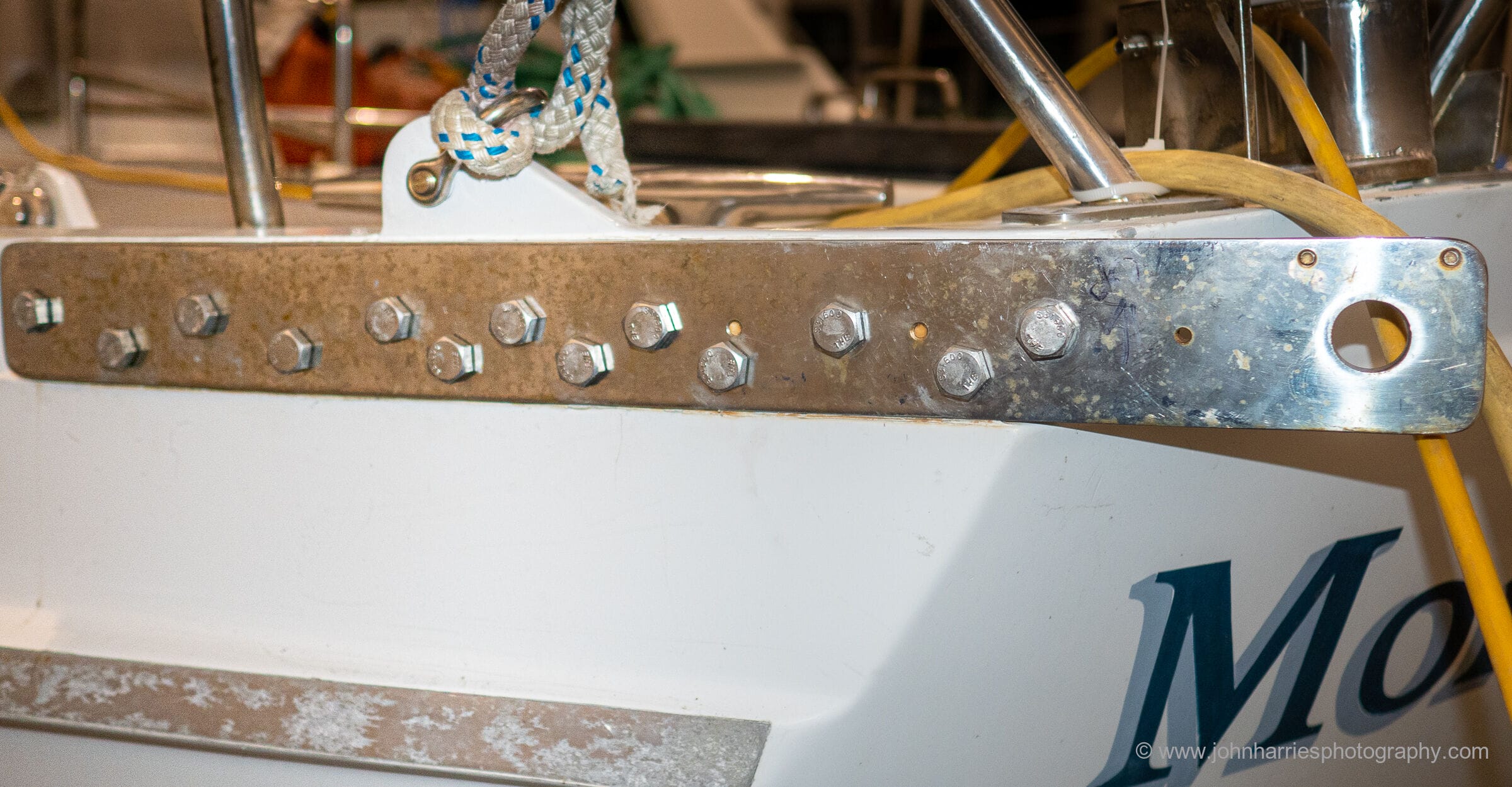
I’ve just been re-reading this post, and I noted a couple of things about your JSD attachment chain plates.
Firstly, I think there is an error/typo in your metric conversion — your 7/16″ bolts are close to 11mm, not 7mm. I was relieved to find this, as when I ran the numbers on 7mm bolts it did not look good at all!
Secondly, for a chainplate design like this which will be subjected to heavy cyclic loading (not pre-tensioned) the 11mm bolts seem quite small as well. If the joint is acting purely as a friction type joint (bolts only in tension), they are OK, BUT if the joint friction is inadequate and the bolts are subjected to shear loads, the 11mm bolts seem inadequate: At your maximum load, assuming the loads on each end of the bridle are equal (dubious?) at least two of the bolts need to share the load equally on each side to avoid possible failure — without taking fatigue into account. Bolts in shear type joints can not be relied upon to share loads equally (or even at all, really).
Maybe I’m missing something? I would recommend that such a chain plate design either has a direct, metal to metal contact with the hull and bolt torques are carefully set (these points should ensure that a friction type joint is maintained and bolts will not be subjected to shear) OR the bolt size is increased to more like 15mm in your case (fewer per side would be OK).
Hi Rossd,
Thanks for catching the conversion error. Fixed now. Also, I’m going to be on the boat today, so I will check the bolt size. I have a nagging feeling that there are two errors here and that the bolts are larger than that. I specified the plates based on this page from Don Jordan: http://jordanseriesdrogue.com/D_5.htm
That said, your comment makes a lot of sense, and I’m definitely checking into this. If I’m still in doubt I will have an engineer look at it.
Hi again Rossd,
I just found my original drawing for the plates, and the bolts are indeed 7/16 or 11 mm. To be honest, after 10 years I don’t remember my rational, but in light of your comment I need to look at this further with an engineer, and I will.
Thanks for pointing this out.
Hi John,
I am working through our JSD launching system for our boat manual. Thanks to your detailed chapters above, everything seems relatively straight forward if we are already running before the wind and waves. What I am pondering is a scenario where we find ourselves hove-to in rapidly deteriorating gale/storm conditions (possibly with a sea anchor deployed as per Chapter 5). Could we consider changing to running with our JSD, or would this be such a lengthy and hazardous enterprise that we should not contemplate changing from one strategy to the other (unless forced to by say rig failure)?
My particular concerns are:
1) Crew fatigue/injury and subsequent errors in the conditions leading to compounding issues.
2) The time taken to come round leading to a broach or leeward fall from a wave when beam on the sea.
3) Needing to use the engine with lines possibly overboard.
4) Keel or rudder wrap situations from the JSD or sea anchor.
Kind regards,
Rob
Hi Rob,
Great question, and one I have thought about too.
The general wisdom, born out by experience, is that the survival system you enter a storm with is the one you live with until the weather gets better.
Having said that, the great thing about heaving-to properly, with or without a galerider off the bow, (or small sea anchor) is that it is very comfortable and stable, which reduces fatigue and makes working on deck much easier that with other systems, particularly active ones like forereaching.
Given that, I see no reason that with careful planning and set up a transition from heaved-to to JSD should not go smoothly. Given that the boat is just drifting slowly to leeward the JDS could be deployed off the stern first and then the galerider pulled in the with anchor windlass, as I detail in chapter five. After that, the main can be clawed down if it’s set up right.
Given that the JDS will already be deployed in the event of a big breaking wave occurring during the transition, the JDS will pull the boat straight and prevent a broach. (It’s important to understand that the orientation of the boat on the front face of the wave is not what matters, rather it’s that the boat is prevented from accelerating down the wave face and crashing at the bottom. See Don Jordan’s explanation of waves.)
The only potential problem I can see is the boat overriding the galerider line but I think that unlikely as long as the crew is relatively quick about retrieval.
Note that I don’t think that any of this would work with a traditional large sea-anchor. Just another reason I don’t like them.
Hi John,
Your “general wisdom” instinctively sounds like really good advice and seamanship, although it places a higher premium on consideration of the weather/sea forecasts before choosing your strategy, particularly with nightfall coming. For us I believe this would mean heaving-to for expected gale conditions. JSD for anything above this which could include any adverse current, exisiting high/cross sea swell or unstable air conditions.
I get your point about the JSD holding the boat back from crashing out of a breaking wave. But whilst hove-to (and near stationary) the JSD will probably be set deep due to the heavy sinker, and it may take some distance / time for the JSD to be properly deployed down-wind in its designed operating mode. So I am not convinced this mitigates the roll-over risk if caught beam on to a breaking wave in the transition phase. The JSD may even accentuate the problem by slowing the rate at which we could make the turn downwind.
I think the trick as you suggest, would be being quick in the transition, so this would be a full-crew manoeuvre for us. Finally John, have you (or any other members) any experience with releasing vegetable oil from (say) the galley sink to calm the wave action to windward whilst transitioning? My concern here is not whether or not the oil will calm the seas (I know it is effective from my mercantile marine days) but that wave/wind action could bring some of the oil back on deck creating dangerous skating rink like conditions.
Many thanks,
Rob
Hi Rob,
Sounds like a good selection strategy and much like what we would do.
I wouldn’t worry about speed of activation of the JSD too much. I have received several reports of JSDs hanging nearly straight down in lulls and still doing their job fine in a big wave. The point being that it’s the boat accelerating that causes the broach, not the wave per se, and if the boat accelerates the JDS loads up very quickly.
Also, I would not worry about being quick in the transition. My thinking is that as soon as the JSD is in the water the boat will be relatively safe from a broach.
And no, I have never tried oil, but would worry for the reasons you mention.
Thanks John,
Excellent and full response as always on this great site.
cheers,
Rob
Hi Rob,
Just now came across your comment on using vegetable oil for calming seas.
I have tried using vegetable oil for calming seas. I was afraid of the possibility of spilling oil inside the boat, making a slippery mess during a storm, so I didn’t want to pump the oil out the toilet or pour it down the sink. In port, I filled a wine bag with a few (probably 3 or 4) litres of vegetable oil, put it into a fabric bag with handles (the kind one would take shopping, that can be carried over one’s shoulder), sewed the bag shut and stored it.
One night, while hove to in a Force 10, I tied the handles of the bag to a line about 30m long, put a couple of holes in the bags with a sail needle, and carefully put the bag out over the windward side.
I never saw the bag again (it was a Force 10, so, of course, I could hardly see anything due to all the water in the air). I did not notice any effect on the seas from releasing the bag of oil. After the storm, I pulled in the line and found that the handles had ripped free of the bag, so, clearly, I didn’t use a strong enough fabric bag.
Whether the quantity of vegetable oil had no effect on the seas, or whether the bag ripped away soon enough that my boat was too far away from the oil for it to have a noticeable effect, I don’t know. I think that if it had been daylight, with less wind, I might have been able to see the effect of the oil on the waves (and whether or not the bag ripped free immediately). At night, in a Force 10, there was just too much spray and too little light to be able to see much of anything.
When you say that you have seen the effect of oil calming seas in your mercantile marine days, was that with vegetable oil, and, if so, what quantity of vegetable oil?
Richard
Hi Richard,
Thanks for your account – love the idea (barring the few teething troubles obviously). I studied nautical science at college and seamanship for my professional qualifications (to 1st Mate Foreign Going). There were accounts in our texts on using vegetable to calm dangerous breaking seas when say effecting a MOB rescue or in launching the windward lifeboats – not life rafts as this would hinder boarding from the water by making it real slippery.
In addition, all our lifeboats carried a canvas bag with a “purse” like opening, and were filled with shredded cotton or oakum which was to be soaked with vegetable oil (carried separately in a 1 gallon container) and attached to the sea anchor or a painter off the bow. I note now in the latest SOLAS regs, this is no longer required for lifeboats or even mentioned, though the sea anchor still is. So perhaps it is discontinued for the reasons we discussed above, or more likely because of the move to fully enclosed lifeboats, protecting passengers and crew from waves and resulting exposure risk.
Funny you should ask now though, as my own first hand experience is in releasing remarkably small amounts of our precious olive oil (please don’t tell on me) over the side through the galley sink, well reefed well down in quite snarly following seas in near gale (but not storm) conditions, surfing down waves at about 7-11 knots under auto-pilot. It was in daylight, during our recent 6 month cruise of the SW Pacific, and for interest only as we were enjoying the sail except for the odd wave strike against the quarter sending spray and some white water across the aft cockpit. I can certainly attest that the wave strike (peak 4-5m) stopped and it appeared to significantly reduce the cresting of the waves behind us, and produced that glassy effect behind and to windward. Truly amazing how little oil is needed. We carried our olive oil in 1/2 litre tins with screw tops, and so it was easy enough to pour a little out onto a few tissues and let the oil seep away slowly, though I admit this was not an elegant solution and likely would have been subject to complaints from the 1st mate if she were not asleep off watch!
I cannot say if it would have helped in a storm and I suspect not as I recall someone writing that the Royal National Lifeboat Institute in the UK has trialled its use and found use of oil ineffective in true breaking wave conditions – I have looked but can’t find that reference now. So for me it remains a “tool in the box”, but not of first resort.
Rob
Hi Rob,
Thanks for that description of your use of olive oil to calm seas. The tiny amounts you were using were most interesting to me. Perhaps the method I used, of a bag of oil punctured with a needle inside a fabric bag would let the oil out too quickly. I will give that some more thought…
Though I have never used oil since that one time, your account got me interested in doing a little research, and I found a discussion of the physics of oil affecting wave formation at https://physics.stackexchange.com/questions/202213/pouring-oil-on-choppy-water-to-calm-it-does-it-work-and-if-so-how/202387
I agree with your thoughts about the use of oil being a ‘tool in the box’, but not the first one used.
RIchard
This may be a mute point … plus I’m new to this subject though I’ve been reading about it for a few months.
Given your thought provoking mental picture of ” … Morgan’s Cloud on the top of a 50’ (15 m) breaking wave and starting down the front … as the drogue takes the strain of stopping the boat from surfing, the load would go to ten times that of our test.”
My question is, should the aft end of chain plate be pointed downward towards the strain while the JSD is under this period of maximum strain? It seems to me that a horizonally placed chain plate on a flat sea is already under slightly increased shear pressure. As the bow points downward on the front of the “breaking wave” (mentioned above) that angle increases significantly. How much does the bow dip … maybe 20-30 degrees. It seems to me this is the period of time that the maximum shear on the through bolts occurs. It seems to me that through bolt shear forces would be lessened if aligned with the forces causing the shear pressure.
I’ve learned much from your discussion group. Thanks.
Hi Clay,
An interesting thought.
I suspect that by the time the JSD really loads up the boat will be well down the back wave face and therefore the load will be pretty much horizontal. (The loading of the JSD does not even start to increase until the boat is on the back side of the wave according to Jordon.)
That said, I really don’t know for sure, but since I have huge confidence in the research and testing that Don Jordan did, and he specified horizontal chain plates I’m not going to second guess him or try to come up with a better angle based on what would be, at best, guess work.
Hi John,
We have our new ACE Sailmakers JSD flaked in a new dive bag and chain + backing plates on order for fitting. I am now going through the bridle details and puzzling over shackle sizing in your article above (and also on various JSD resource sites). I notice a possible anomaly in what you (and they) advise.
Morgan’s Cloud is 52,000 lbs, and JSD maximum load is 30,000 lbs and according to Jordan’s notes the max working load limit (WLL) is 70% of this, or 21,000 lbs per leg. You use Crosby 3/4 shackles to attach the bridle which you write above as having 14,000 lbs WLL (which is below your max leg WLL). But when I check the spec sheet for a Crosby galv bow 3/4 209 Grade A (part 1018491) it gives the WLL as 4.75 t (9,500 lbs), less than half the Jordan calculated maximum leg WLL for MC.
Bonnie Lass will weigh 30,000lbs fully loaded for offshore, our max JSD load is 20,000 lbs and max WLL of 14,000 lbs per leg. For this we are recommended 5/8 shackles, which Crosby data sheet shows as WLL 3.25 t (6,500 Lbs). So this is also less than our Jordan calculated leg maximum load, but not so bad proportionately.
Am I missing something John? Or are the safety factors for the Crosby shackles so big (6:1) that this delta can be ignored for practical application? Should I upsize the shackles (I don’t want to change what is recommended without reason)? Or perhaps take a second set of shackles to replace any sets used in storm conditions, as possibly having exceed their working load limits?
Would appreciate your take on this. Thanks,
Rob
Hi Rob,
I would need to look at the whole thing again to be sure of exact numbers here, but the key issue, for me at least, is this is one of those times we need to think about ultimate fail strength not safe working load. The point being that none of Jordan’s testing ever resulted in these huge loads, or even close. Rather his max loads were derived from calculations of what would be imposed by a “once in a lifetime wave”.
So if we were to try to spec using SWL we would end up with an impossibly large shackle for a situation that probably will never happen. At the time of the post I talked to an Engineer at Crosby and he assured me that the shackle would not even deform until the load reached double SWL at the very least, and there would be almost zero chance of failure until double that.
By the way I just checked the Crosby catalog and here http://www.thecrosbygroup.com/catalog/shackles/crosby-209a-alloy-screw-pin-anchor-shackles/ and it says 7 tons for the 3/4 shackle. Perhaps you looked up the 209 not 209A?
All that said, carrying a spare set of shackles might be a very good idea.
Thanks John, that makes sense to me.
Rob
Hi John,
Very good discussion of the JSD! Helen has just finished attaching the 139 cones to our long lines and now we, more or less, have our JSD finished, except for the bag and the bridle. When building our alloy Dix 43 I welded in some hefty 1″ thick chainplates on either side of the transom, with properly sized holes for accepting 3/4 shackles, thus providing a solid attachment for the boat end of the bridles. On the boat end of the 3/4″ diameter bridles I have spliced in closed cast stainless thimbles. I am wondering about using the same type thimbles on the drogue end of the bridle legs, then a third on the forward end of the drogue leader and shackling the lot together, either with an appropriate Crosby or even a 1/2″ dyneema soft shackle (which I have learned to make -very easy and useful!) This would allow pre-rigging the bridles before heading out, but keeping the bulk of the drogue wrapped up and stored until needed when the bridle legs could be shackled to the leader’s eye. This will alleviate the need to venture aft onto the swim platform to attach the bridles to the chainplates, as they can’t be reached easily from the cockpit ( design error on my part probably).Helen is concerned the extra weight of the thimbles and shackle could cause the bridle to sink/dive and potentially get tangled in our rudder, but I think the drogue will always be streaming back taut.Besides, the lines don’t float There’s simply not a practical place to store the bundled drogue in our aft cockpit design and not have it be constantly underfoot where it could be damaged or cause a fall. As with all safety gear we hope to never deploy it in anger, but feel better knowing we will have some “brakes” on the boat. Any thoughts kindly appreciated!
Hi Brian,
Hum, I simply don’t know if Helen’s concern is valid or not, and I don’t think anyone else does either since without testing in storm conditions several different times there is no way to know. Just too many variables. I do know that a JSD often goes completely slack in some storm conditions.
So, if it were me faced with the same problem I think I would make up a couple of short leaders for the bridles, just long enough to reach back to a safe area. Then shorten the JSD bridle by the same amount as the leaders. With this set up the JSD bridle can be shackled to the leaders, but the part weighted by the join will be too short to get anywhere near the rudder.
Of course this may not be perfect either, depending of the transom configuration and what’s attached to it to cause fouling or banging of the shackles against something.
One thing I’m pretty certain of is that on no account would I use a soft shackle. Just too much risk of it chafing through or coming undone.
Hi John
I have a question about launching the JSD. I have been hesitant to join the discussion because my experience is so much less than yours and many who contribute. I have two of these drogues – one for a 36 ft sloop and one for a 32 ft motor launch. When I bought them (after reading Steve Dashew’s book) I asked the supplier for his recommendation for launching. His response was immediate and seemed logical but I have seen no reference to the idea anywhere. It was to feed the drogue out progressively from the bridle end. That way the cones closest to the stern engage progressively but all the (increasing) load is taken by the bridle and rode attachments. There is no load to speak of on the undeployed part. This can be done without haste until the drogue is half deployed, and then the reminder must be allowed to stream out as well. Until this point the drogue could even be retrieved. What do you think ?
Allow me to say that this site, and the insights you are providing, represent a marvellous contribution to marine safety and sailing knowledge. You are truly to be congratulated !
Best wishes
Bob Buchanan
Hi Bob,
I guess to really opine on this in useful way I would have to try it, but it certainly an interesting idea. That said, I have not heard of problems deploying a JSD the conventional way. The key we found in out testing was to flake the drogue into a sailbag, throw the end out, and stand back. And I guess that last part would be the big reason that I would stick with the conventional method: I just don’t like the idea of a crew having his or her hands on the drogue during deployment, particularly since its going to blowing stink with very violent motion until the drogue is all the way out.
Hi John, I haven’t seen any discussion of bridle length here or elsewhere. The bridle length relates to the angle each bridle leg makes with the transom, which in turn relates to the magnitude and direction of the forces placed on the stern attachments. This angle should NEVER be less than 45 degrees, otherwise the maximum tension in each leg of the bridle will exceed Jordan’s specification of 70% of design load for the stern attachments. This assumes no yaw, which intuitively seems like it could be a safe assumption that as the drogue approaches peak load, the vessel will be pulled “square” via the bridle and each leg, therefore, loaded equally. However, in Jordan’s USCG report he describes a drogue test where the vessel experienced a +/-10 degree yaw. For a possible 10 degree yaw, a 60 degree angle between the bridle and the transom is the best choice. In fact, it is worse above and below that value — in other words, longer is not necessarily better. Even at 60 degrees, each leg will see 74% of the design load, which exceeds 70% a bit, but is the best that can be done when accommodating a 10 degree yaw. 60 degrees seems to be a generally reasonable value for other angles as well. So I’ve concluded that the ideal length for each bridle leg is equivalent to the width of the transom — no more, and no less. I think I’ve worked it out right but it’d be good to double check.
Best,
Chuck
Hi Chuck,
I seem to remember that Jordan specifies bridle length, although right now I can’t find the information. I’m pretty sure that when I ordered mine from Ace they had the numbers in terms of multiple of transom width. One thing I do know is that all JSD’s that I have seen have bridles that are substantially longer than one transom width. I would worry that a bridle that short would place off axes bending forces on the chain plate ends when both legs were fully loaded up.
You can read about the bridle here: http://www.jordanseriesdrogue.com/D_5.htm
Don Jordan recommends 2.5 times the distance of the attachment points for each leg of the bridle.
Hi Again,
Found it: bridle length = distance between attachment points X 2.5
Ah excellent, thank you gentlemen for finding that!! (I do wish though that there was some discussion of why, just because I like to understand.)
Interesting. I just re-consulted the Coast Guard report (http://www.jordanseriesdrogue.com/pdf/droguecoastguardreport.pdf) and, expecting some discussion on the bridle design, found nothing. So I will have to guess.
The bridle, given that both legs have equal length, will form an isoscele triangle. IMHO it would be ideal if the bridle legs continued back inline with the hull but of course this cannot be reached. So I suspect Jordan tried to find the best compromise between the angle of the bridle legs to the hull line, and the bridle leg length. Make the bridle too short and both legs will be spreading load evenly only on certain (short) events, thus applying much more load as necessary to the single leg, and giving the boat a really jerky yaw motion with a lot of shock loads. Make it too long you might have a similar effect as the boat yawing back to the “ideal” position would take too long, resting on a single leg for most of the time.
The 2.5 times the attachment width design gives an angle of approx. 78.5 degrees to the transom when both legs are under equal load. It seems to be a more or less ideal compromise – sorry but I didn’t find anything better at the moment.
Thanks Ernest. The amount of rigor in the USCG report is fantastic. But yeah, there are some things like the bridle setup that did not enjoy the same level of description. Here’s where I’m coming from. With the 78.5 degrees angle, a thought experiment should convince you that at a yaw of 11.5 degrees or greater (i.e., the drogue is off the center line by 11.5 degrees), one of the bridle legs (and its attachment point) will be taking 100% of the load. This is ok, except as you approach the design load — because we’ve designed the attachment points to 70% of design load. If you work out the forces, with the 2.5x attachment width bridle, at the design load the force on one attachment point will exceed the specified 70% limit with just over 4 degrees of yaw. It could very well be that the kind of wave scenario that results in reaching the design load will cause the vessel to “square up” with respect to the bridle and thus have little to no yaw. But then there is the full-scale drogue test in the USCG report (section 4.3) where +/-10 degrees yaw is described. I just don’t know.
Of course I’m going to stick with 2.5x because I’m not the expert — just wish I understood more of the rationale behind some of the choices. Part of the confidence for me is derived from feeling satisfied that things make sense. And this is one system I really want to be confident in!
(If I’m really that concerned about it, I can always over-spec the attachment points.)
Best,
Chuck
Hi Chuck,
Perhaps a little JSD history will help with your comfort levels:
Jordan did the original research that resulted in the CG report and published in the belief that there would be an immediate take up of the technology. That did not happen. Sadly people were simply not willing to wade through the science to understand what a breakthrough the JSD was.
So later, he wrote the much simplified explanations, that now appear on the JSD and Ocean Brake sites, that helped get the JSD out there so people could see how well it worked.
That said, I’m absolutely comfortable that anything Jordan wrote in that simplified paper was based on hard science and calculation. This was a guy who designed high performance airplanes for a living and so I simply can’t believe that he would make a recommendation without doing the required calculation.
Hi Chuck and John,
I found a site that may have some interesting information on load distribution using a bridle: http://www.ia470.com/primer/rigging.htm and scroll down to “Bridling”.
What you can see here is that the load on each leg depends on its angle to the baseline, the more this angle is near 90° the better the load is distributed. FWIW, approximating Don Jordans 78.6°into the table listed on the side each bridle will take 0.5 of the drogue design load multiplied by a factor of 1.02, given that the boat doesn’t veer off the centerline.
By veering off the load would quite soon be transferred to only one bridle leg. Having stretch here will help IMHO as the “slack” leg will still receive some of the load, I assume DJ calculated around 30% remaining and 70% on the leg taking the main load.
Would the bridle leg be shorter the factor mentioned above would be higher, and the load when veering would near 100% to one leg a lot sooner.
Also, when looking at the legs being levers, shorter levers would have a harder time straighting out the boat because the center of rotation (the point where the bridle legs meet) would be closer to the transom, reducing the straight-out effect.
I still believe that 2.5 is a compromise between optimum angle and managability of the bridle during deployment and retrieval.
And one more, see https://www.northernstrands.com/sling-calculator.aspx Using the 2-leg calculator, enter e.g. 30000 lbs for the design load, 25ft for the bridle length (assuming a 10ft transom width) and 24.5 as the height (calculated from sqrt(25×25 – 5×5)). The result will show you that the average load on a single leg is only a bit more than half of the design load.
Shortening the legs to say 1.5 attachment width will result in 600lbs more load on the leg. Leg same length as the transom width add another 7300lbs of load.
Making the legs longer, e.g. 3.5 transom width, will reduce the load on a single leg by mere 200lbs in comparison to DJs 2.5.
Which makes me believe even more that 2.5 is a well calculated compromise.
Hi Ernest! Very cool stuff, thank you. That makes sense to me. The situation I’m wondering about is when the force on the bridle is at an angle, i.e., not perpendicular to the line between the attachment points, as is depicted in those diagrams and which would be the case for a weight suspended from a level ceiling with equal length legs. See for instance this short video: https://www.youtube.com/watch?v=rAXBmWlryO8
The fact that Mr. Jordan chose 2.5x tells me he was not concerned with this situation, so I will stop wondering about it, and proceed on the assumption that as the drogue loads up toward the design load, the vessel will pivot / square up and the force on the bridle will have little or no angle. I have no personal experience with how a vessel with a drogue behaves in such conditions, and hope I never do! 🙂
Hi Chuck,
very informative, thanks for the link.
The difference I see between towing and a drogue is that when towing the biggest load is on the end of the line, and having “a life of its own”, while when towing a drogue the load is the drogue by itself, in its full length. I would not expect the JSD to be perpendicular to the transom all the time, but the load (drag) it executes should not be more than 10° off center as even the cones closest to the boat execute drag, trying to straighten things out. I would rather expect the JSD to meander behind the boat (like a snake), unlike when towing another boat with an otherwise unresistant towline.
John would you recommend using soft shackles instead of the Crosby 209A shackles for attaching the bridles to the chainplates?
I have just ordered and received a custom 3/4″ (or more not sure) dyneema Jordan rogue, for my Hylas 63, which weighs about 40 tons, or 90,000 lbs.
I will hook it up to a SS plate I will sandwich in between the bases of my Simpson Lawrence blue water davits and three backing plates with a total of 12 5/8″ bolts.
I need to determine the width of the SS plate I will add, and the size of the shackles if I go with the Crosby. I was thinking of putting a 1″ 209A with a working load of 12.5 tons but it weighs 5.3 lbs!
Hi Alberto,
No, I would not use soft shackles in that application. It might work, but I don’t want to be the one to find out that there’s an untended consequence of making this change. It would also be a challenge to round and smooth the holes in chain plates so they would not chafe the soft shackle.
My current thinking is to use Dyneema bridles with loops in them and cow hitch the loop around the shackle without any thimble. The advantage of this approach is that the cow hitch will pull tight around the shackle, and after that happens there will be pretty much no movement of the rope to cause chafe. With a soft shackle through the chain plate, there will be constant movement of said soft shackle as the bridle loads and unloads.
Also, in you application, I would want to be very sure that the deck in the way of the davits can actually take the load that this very heavy boat can exert on a JSD. If there is any core in the area, then it will need to go, and additional laminate may be required to spread the bolt load.
I’m not familiar with the behavior of a JSD, having not yet seen one in action (either first-hand or video), but am in the process of planning mine out. Is there any chance, with cow-hitched bridle eyes or loops directly on the shackle, of forces in the horizontal axis causing the eyes to want to slip around / rub on the shackle? Or, if they manage to grip the shackle without movement, possible fatigue in the Dyneema fibers from bending back and forth in the horizontal?
Hi Chuck,
No, I don’t think either of those will be a problem. That said I would upsize the bridles to take into account and weakening from the cow hitch
I’m curious how other highly experienced offshore cruisers, like Susanne Huber-Curphey and Fatty/Carolyn Goodlander have their JSD set up. Do they all use chainplates?
Don’t know where to ask this question so I am asking it here. In short as I understand the term drogue it is a brake to slow you down while the series drogue is more like an anchor to hold you against the seas. My setup is the usual through the chocks to the winches arrangement which I realize is probably not useable accept maybe as a last ditch desperate act to safe lives. The more I read, I have the book DDDB, and articles here, since we are stoping our boats and riding out the storm why are we not deploying off the bow. The whole front architecture of the boat is designed to handle passing through water where the stern is designed to leave it behind. In DDDB there is incident after incident of damage done by the occasional wave breaking on the boat. My experience anchoring stern to weather with my flat stern is this is just plain wrong, and yet the series drogue does just that. When I bought the drogue I am sure it was described as a brake and I would still be sailing and I need to or could be actively involved. Now I know I was misinformed. Since it is going to take time and money to modify my boat with drogue chain plates and since loosing your drag device happens and something to take its place is needed I have added a Shark Drogue which is quite compact and easy to deploy and recover, thus is more likely to be used early or at least at the right time. So, the question is why aren’t we deploying this like a parachute anchor since it seems to behave as one? Thanks
Hi Daniel,
Short answer: a JSD is not used from the bow because it works very differently that a sea anchor and boats generally lie more quietly with less yawing when held by the stern.
Long answer: https://www.jordanseriesdrogue.com/D_14.htm
Longer (and best) answer: https://www.jordanseriesdrogue.com/pdf/droguecoastguardreport.pdf
A few years back, I texted with Fatty Goodlander about using a JSD from a bow cleat and stern cleat to form a bow-biased triangle line, as a better sea anchor than a parachute-type sea anchor to hold a heaved-to position. The main advantage being that a “JSD sea-anchor” would be much easier to retrieve than the parachute-type sea anchor…
… i.e. you would get more than one wish from the sea anchor genie. 🙂
The only reason he said he couldn’t do it was because his wife Caroline shook her head “no” to the massive amount of sewing work she would have to do to lengthen their current JSD. He was half-joking of course…
…but seriously, we both had apparently come to the conclusion that it would take a really long JSD at some angle off the bow to hold a heaved-to position. If the JSD were too short, the massive forces would pull the JSD cones free and you would lose the sea-anchor effect, i.e. the bow would come around for a few seconds/minutes.
Hi Charles,
I guess I’m not really sure how Gary could know that without trying it in real world conditions.
There’s a simpler answer to stopping fore-reaching when heaved-to that Phyllis and I real world tested in large breaking waves, that is both easy to deploy and retrieve: https://www.morganscloud.com/2013/06/01/stopping-wave-strikes-while-heaved-to/
Also, if you are interested in making heaving-to safe I strongly recommend Lin and Larry Pardey’s book, linked to in the above linked post.
That said, in a true survival storm I would still want a JSD. Full reasoning behind that opinion here: https://www.morganscloud.com/category/storm-tactics/online-book-heavy-weather/
https://www.morganscloud.com/2017/04/22/determining-when-heaving-to-is-dangerous/
Correct. He couldn’t. We were just talking theoretically.
What I was hoping for is that I could use a JSD for both heaving to and as a trailing warp, i.e. one relatively easily retrievable, multi-use tool. I agree that one needs a JSD for the latter, of course.
What’s nice about the JSD (I’ve read and I hope) is that you can adjust its drag force up or down depending on wind/wave conditions. You can’t do that with a parachute-type sea anchor, i.e. it’s pretty much all-or-nothing, right?
…and yes, I’ve read several of the Pardy books. I think that’s probably where I first read about the heave-to off a chute procedure and then came up with the JSD heave-to idea from that.
I’m hoping maybe someone has tried it in real life and can weigh in?
My fiberglass boat has a canoe stern, with a stern hung rudder. A boomkin and eventually self steering aft of that.
I’m trying to figure out the best drogue chainplate arrangement. In order to have enough beam between the bridle ends, I imagine the chainplates would be installed approximately level with the jib sheet winches. But this will mean that the bridle runs along the hull for a time. Would this be an increased chafe risk? Also an increased risk that it could become fouled on the vane gear?
Curious if you have seen any examples of chainplates on a canoe stern, or have any thoughts on the subject?
Thanks!
Hi Dhornse,
Yes, that stern set up is going to be a problem, and to be realistic, I’m not sure it’s solvable. I guess if it were me I would use sheathed Dyneema for the bridles and go up at least one size to take the chafe and then experiment with Stein’s batten idea to keep the bridles off the vane: https://www.morganscloud.com/2019/07/12/series-drogue-learning-from-randall-reeves/
However, even with all that I would expect that the vane might get damaged in a JSD deployment since it projects so far from the the stern and chain plate locations. On the other hand if the JSD has brought you safe through a survival storm, a damaged vane is a comparatively small price to pay. On that note: well worth fitting a good autopilot for backup.
Hi Dhorney,
One other thought. If faced with this situation, I think I might consider the Pardey Bridle as an alternative to the JSD. See my thoughts here:https://www.morganscloud.com/2018/11/14/storm-survival-faq/
Hi Dhornsey, I’m curious to know if you came up with a solution? I have a Victoria 30 (in US built as Morris or Leigh 30) with a canoe stern and vane steering. However as the rudder is keel-hung the vane gear only sticks out 30 cm or so from the stern which I suspect is less than in your case. But even so lines get fouled on it. Its particularly popular with the inflatable dinghy when I’m towing it, and trolling lines. I currently have a para anchor which I would deploy from the bow and if that isn’t successful try the Pardey method. I’ve never had to use it and quite honestly dread having to handle all that kit in the conditions that would warrant it. But the possibility of getting the bridle of a JSD wrapped round vane gear doesn’t appeal either although it sounds like a much better system. I sail single handed a lot and I really depend on the vane steering.
Hi Colin,
See this chapter for a solution that I think would work for you:
https://www.morganscloud.com/2019/07/12/series-drogue-learning-from-randall-reeves/
Also this one may help too since it’s about a deployment on a double ended boat:
https://www.morganscloud.com/2013/06/01/real-world-jordan-series-drogue-deployment/
I am trying to work through the design of the chainplates for the JSD bridles. There are many things to consider and varying opinions as to what the design load should be. 70% of displacement or 70% of drogue design load for instance. To get a feel for things, I am field checking your installation. This raises some questions, but is a good starting point for learning more, since you’ve consulted with engineers.
When I look up the Crosby Screw Pin Shackles https://www.thecrosbygroup.com/catalog/shackles/crosby-209-carbon-screw-pin-anchor-shackles/ I see a working load limit of 4.75 tons or 9,500 lbs for a 3/4″ 209 shackle. Ultimate strength is 5 times the Working Load Limit or 47,500 lbs. The table also states that the Working Load Limit will be reduced for side loading applications. Since the bridle will be working back and forth, and your chainplates are vertically oriented, I think this note is relevant.
Your article states “safe working load of 14,000 lb (6350 kg) and a deform point of twice that”. Am I looking at a different shackle? Can you provide your source? Where did the deformation loads come from.
The pin diameter for a 3/4″ Crosby shackle is listed as 0.88 inch. I assume you have a 1 inch diameter hole which leaves a load bearing area in your 2.75″ W x 0.5″ thick plate of 0.875 sq inches. calc: [(2.75 – 1) * 0.5 = 0.875 sq in]
If we use 30,000 lbs/sq in yield strength this gives your chainplate a yield strength of 26,260 lbs. calc: [30,000 * 0.875 = 26,260 lbs]
This agrees with your comment in the article: “Interestingly, the weakest point (every system has one) in all of this is the hole in the chainplate, which will fail at about 26,000 lb (11,800 kg).”
You go on to say: “Since it is unlikely that more than 70% of the peak load will come on one bridle leg, this is well within acceptable limits.” Based on the previously stated displacement of MorgansCloud: “MC displaces 52,000 lb (23,500 kg) fully loaded) … playing with the numbers: If a JSD design is 70% of Displacement, then 52,000 lbs x 0.7 = 36,400 lbs, and if a bridle design load is 70% of the JSD Design, then 36,400 lbs x 0.7 = 25,480 lbs … so you are right at design as long as all factors of safety are built into the preceding design numbers. Although, I am not clear on the shackle design numbers.
Just for fun, lets check the chainplate suggestion on the JSD website: https://www.jordanseriesdrogue.com/D_5.htm. “For a load of 14,000 lbs, a strap ¼ x 2.25 x 18 inches attached with six 3/8 bolts would provide a conservative design.” This would be the design load for Jordan’s theoretical 20,000 lbs boat. Applying the math again, if we assume a 3/4″ shackle hole, then the available metal for taking the load is: (2.25″ – 0.75″) x 0.25″ = 0.375 sq in. At a 30,000 psi yield: (30,000 x 0.375) = 11,250 lbs which would seem to be under the 14,000 lbs load requirement. If we go down a shackle size to a 1/2″ shackle and assume no clearance in the hole size, for a 0.63″ pin, the math is (2.25 ” – 0.63″) x 0.25″= 0.405 sq in (more area due to smaller pin hole) then 0.405 x 30,000 lb yield = 12,150 lbs … which is still under the 14,000 lb design load.
My misunderstanding here could be that when it says “for a load of 14,000 lbs” it is referring to the drogue design load and not the bridle design load, although that statement is under the section titled “Attachments on the Hull”…. it isn’t explicit but does raise questions.
If I check the breaking load of the chainplate at 26,000 lbs against the size of the bridle rope, it would seem that the bridle rope is undersized as well. Since everything doesn’t fall into place when I do these napkin calculations, I am wondering where my misunderstanding lies. Since I want to install chainplates on my own vessel, I’d prefer to iron out the details before cutting steel.
The easy answer is to consult with an engineer, rigger, or designer. This puts the liability on someone else, but my piece of mind is found in seeing the numbers work out. If the recommended sizes were overly large by my numbers, I could write off the difference as being due to the side loading factors, but so far, the numbers point to either thin margins or undersized per the JSD recommendations.
Your perspective is appreciated.
Hello John,
Your JSD chainplate journey sounds a bit like mine – lots of questions and few satisfying answers.
I’m a professional software engineer, so I have the mindset, but neither formal training nor experience in mechanical engineering. I tried to hire a marine engineer/architect to help with my design. The few that responded to my inquiries were either too busy or my project too small. Eventually I hired an aeronautical engineer, with the goal of not only specifying my own design, but releasing the work for the benefit of the larger community. However, the work was so fraught with mathematical errors that I didn’t feel comfortable sharing. In the end I gave myself a crash course in mechanical engineering and designed the thing myself.
I will share some of my findings along the way, with the caveat that I’m not a professional and I may have gotten things wildly wrong. This is use-at-your-own-risk information, in other words.
Design load is not displacement. System design load is specified by Jordan in section 6.2 and figure 26 of his USCG report. Everything relates to design load thereafter. Each leg of the bridle therefore has a design load of 70% of the system design load.
The term “design load” has a specific meaning in mechanical engineering. My personal interpretation of that meaning is that it’s the max load that will ever be encountered. In my design, permanent deformation (but not failure) is acceptable at the design load. According to https://ntrs.nasa.gov/archive/nasa/casi.ntrs.nasa.gov/19880005638.pdf, “Design loads given – for this case no safety factors are required and margins of safety of 0.15 or greater on failure modes are typically acceptable.” (Note my hull is fiberglass.)
I concur with your assessment of the chainplate example attributed to Jordan: “For a load of 14,000 lbs, a strap 1/4 x 2.25 x 18 inches attached with six 3/8 bolts would provide a conservative design.” This is a wholly unsatisfying specification because it does not address strap material, hull material, reasoning behind small thickness, reasoning behind large width (relative to standing rigging chainplate widths specified for similar strengths in well-known sailboat architecture textbooks), bolt pattern, or parameters for design loads other than 14,000 pounds.
In the given example, assuming a shackle pin diameter of 5/8 in., the bearing stress on the chainplate hole is 89,600 psi. The bearing strength of 316L stainless steel is about 69,700 psi. Therefore, it would seem that the given load of 14,000 pounds would likely cause a 316L stainless steel chainplate of the provided dimensions to fail under bearing stress, even for new material with no weaknesses. It is challenging for me to see how this is a “conservative design.” A shackle pin size of 15/16 in or a lug thickness of 3/8 in would be necessary to reduce the bearing stress enough to meet a 15% margin of safely.
It is unlikely Jordan got it wrong, but without context it’s hard to generalize the given chainplate specification more broadly. If we assume that by “14,000 lbs” he was referring to the design load of the overall system, i.e. only 70% of that for the chainplate, then the bearing stress comes in just under, but pretty close to, the acceptable stress for new 316L stainless.
Something else to keep in mind, if your hull is a composite material, that will likely end up being one of the weaker parts of the system. There are some old but great papers from NASA and the US Air Force available online about composite joint design.
I saw a couple papers that showed a staggered (i.e. not inline) bolt pattern results in diagonal stresses between the fasteners. Such stresses would be off-axis for a composite material laid up with the fibers in 90 degree orientations, as my hull is, so I went with an inline bolt pattern.
As long as the shackle pin is “square” in the chainplate hole, I personally don’t see this as a case of side loading. Use washers around the chainplate and through the shackle pin as needed. I believe there may be some point loading on the pin, but according to https://web.archive.org/web/20181106061222/http://www.oceanbrake.com/configuration-assembly/, allegedly Jordan specified a bridle leg length of 2.5 times the width between the attachment points. That gives an angle “off square” of only 11.5 degrees assuming the stern-hull junction is exactly a right angle. (In practice the hull may have begun sloping toward the centerline again near the transom, which reduces that angle.) The attachment of the bridle leg on the bow end of the shackle–which will be oriented horizontally under load–may help with this, but I’ve not analyzed that aspect rigorously.
A couple knowledgeable engineer-types I spoke with were concerned about the bending moment (this may be incorrect terminology – I’m recalling from memory) at the chainplates. Because others have deployed their drogues in storm conditions without special consideration for bending moment, I did not concern myself too much with this. However, this is not entirely satisfying. I’m going under the assumption that as the system loads up, the force vector becomes more and more “square” thus reducing the bending moment on the chainplate. I.e., that the yaw-inducing component of the force diminishes as load increases.
Another topic that I have not seen discussed is chainplate fatigue. Jordan’s own fatigue study focused on the drogue itself, not the attachment. I estimated that the system I designed would be safe from fatigue for 11 full days of storm waves.
For peace of mind – what it all comes down to – I highly encourage you to give yourself as thorough an education in mechanical engineering as possible, then work it out to your own satisfaction. And if you’re able to, definitely work with a professional engineer. Even in this event, your self education will be a fantastic foundation for doing so. (Be prepared to check/verify their work, however.)
If you might find it helpful, I’d be willing to share privately with you my own 17-page design document, provided the “use at your own risk” caveat. It includes references and my reasonings on things. Having a set of critical eyes on it would be helpful as well. (I was unable to find a professional engineer willing/able to review my design.) When I showed this design to the boatyard, the project manager asked if I wanted a job lol.
I still hope that some day I’ll have an opportunity to work with an engineer to provide the community with rigorously-designed plug-and-play templates or guidelines for the “missing links” not directly addressed by Mr. Jordan’s great work.
Best of luck,
Chuck
Hi Chuck,
I to did a complete rethink of my chain plates last fall and will publish something about that in due course. Summary, it’s a complex subject without definitive answers, just like most of boat stuff! That said, the comforting thing is I have never heard on a JSD chain plate failure, so that’s to the good and I think indicates that Jordan was pretty conservative on what he told people.
Chuck,
You are my brother of a different mother… great post. I’m feeling that we are in sync on these issues. How can I get a copy of your design guide? I’m not sure how AAC members can contact each other.
I also have a fiberglass hull. I was planning on adding some thickness and a backing plate, but would like to have what I do based on a design, rather than a “bullet proof” – overdone, attempt at safety….and never really knowing if I got it right…. until the reality field test.
Personally, I don’t like overdone. I like designed right. Lets collaborate.
John
Hi John,
While I agree that getting the engineering right is the correct approach, my own work last fall left areas of uncertainty, and I think with a fibreglass boat there maybe even more of those areas, so, if it were me, no matter how much engineering I had done, I would still overbuild a bit, particularly in beefing up the laminate.
That said, as far as I can see, Jordan already had substantial safety factors built into his design loads, so, if we work towards them I think things are good.
To John R. – I had a review of the site’s Comment Guidelines, and posting contact info appears to be acceptable. Feel free to reach out to me at cbatson3 at “the mail that begins with G.” Hope that makes sense. 🙂
To John H. – Looking forward to your future article on chainplates. Your writings are always immensely enlightening! And this is a topic that is near and dear.
One of the things which make these designs difficult is the use of different standards for design and ratings.
ASME B30.26 Lifting Hardware standard utilizes breaking (ultimate) strength.
Structural engineers base their designs off of yield strength, which is the load which defines the upper limit of elastic deformation, where when the load is removed, the part returns to its original dimensions.
A load/elongation chart is very linear below yield. When the load is removed, the part returns to its original shape. Between yield and ultimate loads, the chart will curve as plastic deformation starts rearranging the material structure in a permanent way. In the plastic deformation stage, the part becomes deformed or stretched. At ultimate strength, the forces exceed the ability of the grain structures, within the metal, to remain attached to each other, and a failure of breakage occurs.
So Crosby doesn’t design to yield strength, and you can’t tell directly from their product information what load the shackle will typically fail at. You can infer the yield strength from their Proof Load, which is the average force that can be applied before deformation occurs. Crosby states that the Proof Load is twice the Working Load Limit (WLL). This is a good indication of the Yield Strength.
They also state that the Design Factor is 6:1. Design Factor is defines as: “an industry term denoting a products theoretical reserve capability; usually computed by dividing the catalog Ultimate Load by the Working Load Limit. So we can conclude that the Breaking Load is six times the WLL.
It is also worth noting that Crosby rates their shackles fatigues resistance to a standard of 20,000 cycles at 1.5 times the Working Load Limit. If you are selecting a shackle for the JSD bridle, if the design load is in the range of 1.5 times the WLL, it shouldn’t break from fatigue or deform under peak loads.
My conclusion from this information is that John’s statements regarding the loading of his 3/4” Crosby shackle are within reasonable design loads.
It should be noted however, that there are two G-209 shackles:
G-209 with a 4-3/4 ton Working Load Limit: 9,500 lbs
G-209A with a 7 ton Working Load Limit: 14,000 lbs
Dimensionally these two shackles are the same but the “A” designation indicates Forged Alloy Steel – Quenched and Tempered with an alloy pin.
The final consideration is the point loading or side loading of shackles. Crosby has a Technical Data Sheet – TDSSHALOAD which states several important considerations.
Point loading – spacers should be used to hold the load in the center of the pin and not allowed to slide over to one of the ears.
Pad eye width – if the attaching links or pad eyes are equivalent to or larger than the shackle bow cross section diameter, no reduction of the WLL is required.
This document has a table for recommending a WLL reduction for conditions where for narrow pad eye width, off center loading or side loading. The reduction in WLL to accomodate these conditions varies from no reduction to a reduction of 50%. (for a 90 degree angle). Relative to JSD, angles between 11 to 20 degrees only require a WLL reduction of 15%.
A final design factors is the recommended clearance for Pin Holes. Up to 5/8 shackles, a clearance of .06″ or 1/16″ is recommended. 3/4″ to 1-1/4″ the clearance increases to 3/32″ or .09″
So in summary, the shackles will deform at twice the WLL and fail at six times the WLL rating, as long as the load is straight on. To assure the load is straight on, provide spacers to center the pad eye or link on the shackle pin. For minor angle deviations, such as those which may be encountered with a bridle, figure in a 15% reduction in these numbers. A final consideration is that in specifying a 209 shackle, double check whether you need the alloy version (209A), which is about 50% stronger.
Hi John,
Great analysis, thank you. Some things I knew and several I didn’t. One thing on yield strength is that I did chat with a Crosby engineer and verify that it is twice SWL as you say and I say in the post. Also, I specifically linked to the 209a shackle. In fact that’s the only one we generally recommend: https://www.morganscloud.com/2007/09/01/which-anchor-shackles/