

One of the most frequent questions we get about the series drogue designed by Don Jordan (the storm survival gear we recommend in this Heavy Weather Tactics Online Book) asks if I can recommend an attachment alternative to the chainplates we installed on our boat.
And, in some cases, the questioner has even stated up front that they are not going to install chainplates, end of story.
So let’s take a look at the most commonly suggested alternatives to chainplates.
Hi John,
Not to disagree with your calculations and sound argument, but I’ve done several installations where a centralized chain plate is not feasible because of a wind vane or stern hung rudder.
This solution applies to any boat with bulwarks like a Valiant, Cape George etc.
1- Build a substantial area where the hause pipe is going to penetrate the bulwark and hull out of solid glass. No wood filler or foam between the hull molding and deck molding.
2- Buy a beautiful silicon bronze traditional hause pipe with built in horn cleat from a foundry like NewFound Metals or PT Foundry.
3- Install it with a tight fit enhanced with silicone/epoxy so all the load is transferred from the inner part of the hause cleat into the 1″+ of solid glass.
4- All the movement and line friction are external to the hull so chafe cannot occur.
5- Loads are (largely) shared between two mounting points.
6- Load falls upon the highly reinforced hull and bulwark instead of bolts in sheer holding a cleat to the deck.
7- No deck leaks!
Hi Richard,
Just to clarify, I’m not suggesting (or happy with) a centralized chainplate since Jordan calls for two as widely spaced as possible. (Not sure if you are referring to a single chain plate, but did not want any confusion about that.)
Anyway, sure, that would work, I think, as long as the fitting could take that kind of load and we had confidence in the bulwarks on that particular boat. Still, it does put us back to relying on a cast cleat horn. Bad news if there’s a fault in the casting. I don’t know enough about metals and casting to know for sure if this is a likely problem. That said, I do know for sure that casting consistency can be very tricky since I have a friend that had a hell of a time getting a bronze casting done for a rudder quadrant that would meet ABS requirements.
Another option for double enders is to do something like Paul Kirby did and move the plates forward to get the separation required. Might require some faring and machined spacers (G10?) to to get them lined up with the load and give room for the shackle, but certainly doable.
Bottom line, double enders add challenges to this project.
The chainplate itself is easy to design safely. However I suspect that understanding the load paths and structural integrity of the hull adjacent to the chain plates is underestimated since usually material qualities, dimensions and expertise lack. I would argue that in most cases a full scale test with design forces is the only reliable way to qualify the installation of the chain plates. How this can be done in reality, I don’t know. As you suggest hanging the boat onto the chain plates given sufficient weight would work, but … or maybe dragging the boat at high speed backwards ??? Good engineering is realistic measurable testing so how could this be done?
Best Florian
Hi Florian,
I guess that if we want to 100% sure, the only answer is to hire an engineer and have them check the strength of the hull laminate and surrounding area and then spec any required changes and reinforcing.
That said, if in doubt about the area we are going to bolt through, I thinking a simple way to get close would be to just duplicate the reinforcing used for the cap shroud chain plates and then go up a bit.
And then there’s the approach I always take with this kind of thing: overbuild the hell out of it. Might require some extra glass, or maybe G10 backing plate glued in with epoxy, (or both) but not a huge job once one gets at it. Another option would be an aluminium backing plate attached inside with Plexus.
All of these challenges will vary by boat, but I think they are all solvable, and I don’t think we would need to do scary stuff like hanging the boat up by our work to be sure.
RE. cast vs. forged/fabricated fittings.
Casting is not an inherently flawed technique for making this kind of thing. Engine blocks are cast. The Janney couplers that link train cars together are cast.
However, casting is also the preferred technique of cheap no-brand parts shops whose quality control consists of little more than slapping on a “QC Pass” sticker and whose contact information is impossible to find.
It’s not a matter of manufacturing technique; it’s a matter of QC and trust. If the manufacturer refuses to provide some kind of proof test certificate saying it’s good to a certain load, then you’d better think long and hard about trusting your life to it under that load.
RE. chainplate / attachment point design.
It’s easy to do all the calculations for the chainplate itself, and its bolts, and then say “At this point the load is transferred to the hull” and walk away.
That’s risky, particularly on planked wood hulls and on cored fibreglass hulls. If your chainplate is good to 13 tonnes, but the laminate around it starts to buckle or shear at 5 tonnes, you haven’t solved the problem.
There are a lot of things on a boat where you can just eyeball it and, with a bit of experience and foresight, come up with a workable – or even better than factory – solution. This is not one of them. Drogue hardpoints aren’t taking the full thrust of your engine, or even the full holding power of your anchor; they’re taking the thrust of an F-16 fighter jet on max afterburner. They must be engineered accordingly. They’re one of the very few points on a boat where I’d say that no matter how tight your budget and how good your fabrication skills, expert design verification is always called for.
Hi Matt,
That all makes sense. I guess on a practical basis that confirms my distrust of casting since I have never seen any sort of guarantee or certification for a cleat, or even a published safe working load.
And I totally get the benefit of having proper engineering done on the laminate. That said, it’s hard to find someone to take that on so what do you think of my idea of duplicating the cap shroud chain plate reinforcing as a base line?
Also, good point on cores. Clearly the core is going to have to go in the way of the chain plate, just as it should be removed around a shroud chain plate.
Adding a few thoughts on casting.
Like Matt says, there is nothing wrong with casting. You can’t directly compare castings with machined from billet parts as typically the materials are not identical, casting alloys are slightly different and therefore have slightly different material properties. Generalizing, casting grades tend to be slightly weaker with slightly lower elongation to break (they stretch less before breaking) but you really need to look at specific material properties. A typical knock down factor that you might see on a cast part’s material properties would be 10% to account for imperfections in the casting itself. Another thing to keep in mind in terms of materials is that some require heat treating post casting so make sure that your process and material properties you are comparing are for the same heat treat.
In addition to the material differences, casting quality is a really big deal. There are many examples floating around of broken cast pieces where you see enormous amount of porosity or other issues but we should not discount all casting because of it. These issues can arise from the original part design, the pattern design or from process control of making the actual castings. While destructive testing is great, it isn’t practical on 100% of parts as you would have nothing to use and it is expensive so most commonly, X-ray inspection is used. There are a whole set of standards for this so if you are buying a casting, simply ask what standard they follow, read it to make sure it seems appropriate and ask for the inspection report. For a structural part, they either need a sampling plan with destructive testing or X-ray testing. Along with the inspection report, you will also typically get a set of certs for the material and any heat treating/HIP/etc that was done, just make sure the original order form specifies you are getting all of these.
The majority of high volume parts that have real 3D shape to them are cast, sometimes with post machining. I have designed tons of cast parts and beyond needing to build in more time for the vendor to make the pattern, dial in the process and do process validation, I have never had any issues and I design mechanisms for capital equipment where stress is often high.
Eric
Hi Matt,
I’m with John on this. Just overbuild the sucker!
The key element of my bulwark scheme is that the load is indeed transferred directly to the hull with little reliance upon bolts. (Take a close look at a traditional horn hawse pipe https://www.porttownsendfoundry.com/hawseholes) (scroll to the hawse cleat section) If you don’t chrome plate one of these you can do an excellent visual examination, or magnaflux it if you want. If the hull is cored at that point, or there is a wood or foam filler between the hull and inner bulwark, remove it and replace with solid glass. Now we could do a FEA analysis of the aft quarters of the boat and throw in all the guess factors about the actual load paths and laminate quality. I’d rather just make it hell for stout (1″ solid glass spread out over 2′ length of bulwark) and spend my money going sailing. I wouldn’t try this on a carbon/nomex wonder boat though!
ps For all of us who hate varnishing silly teak cabin top handrails, check out PT’s collection of hand rail fittings.
Hi Richard,
Good point. We used to have wood hand rails and varnishing them was the most hated job on the boat. Replaced them with SS and do not miss them!
Hi Richard,
Yes, I looked at that horn hawse pipe, and I agree it’s a really nice piece of kit. That said, I’m still a little worried about the two cast horns taking all the load although I would be the first to admit that’s just a gut feeling and may easily be wrong.
Hi John
Your gut feeling could be right. If I were concerned I’d build a fixture made of solid 1″+ glass, take it to a rigging test facility, and pull til it broke!
Hi Richard,
That makes sense. I have a friend that built some loverly looking, and massively strong fittings, including a gooseneck, out of glass and epoxy.
Hi Richard and John,
To a degree I agree with the overbuild it philosophy. My opinion is that it does take some thought on what overbuilding means. Just like some people think that 1000 lb concrete blocks are massive so adequate for moorings for 40′ boats, some people don’t have the right intuition for what overbuilding actually means. To me, overbuilding often is doing a very rough calculation to get in the ballpark and then using a generous safety factor to account for any inaccuracies in the calculation although sometimes I use intuition but then again my job forces me to evaluate these sorts of problems regularly so I have a fair amount of practice.. In the case of bolts pulling through, if you don’t know what the layup of your hull is, use the worst case layup you think possible for determining the strength, don’t choose the highest numbers you find and that would seem reasonable to me.
Also, I think that Stein’s suggesting on composite chainplates is a good one. Probably a bit more engineering for the average Joe but potentially a great solution.
Eric
Hi Eric,
That’s a good point. My misunderstanding of the way bolts share loads, or rather don’t, is a good example of the kind of mistake a lay person can make around engineering.
Hi John.
I agree completely with your conclusions, of course. Chain plates are the only really good solution. However, the words “chain” and “plates” might be misleading, in their strong indication that only solid metal can be used. I think that’s the right choice in most cases, and I know you’re aware of alternatives, but just for the record:
One could benefit from using fibres rather than metal. This can make it easier to spread the loads better into the hull. My guess is that this option is mostly for very lightly built boats. I have made this type of “chain plates” for cap shrouds several times. The oldest are still sailing hard and have been for 25 years. (Formula 28 racing trimaran Mirage). They save weight and give light structures more integrity as it becomes one uniform part with gradual dispersion of loads rather than joined parts with point loads.
In real life, I think fiber versions of chain plates for JSD will probably only be a good choice if it can be made when the boat is being built, or perhaps during a complete refit. The reason being that one might have to do bigger changes to a larger area to make it work well than with metal chain plates.
If still going for it, I’d consider using long narrow ribbons of UD S-glass wet pregged (epoxy) and distributed on the inside of the hull and then loop it out of a hole at the corner between stern and hull. Similar length on both sides of the loop. It needs to be tensioned a bit while laying it out to make most of the fibres share the load. The loop might need a metal surface put on the inside while moulding, if metal parts are to be attached there. The loop hole 🙂 in the hull will have small cavities that need to be filled with epoxy putty to avoid leaks.
The core principles, anyway, remain the same:
– Attachment points outside of the deck area, to eliminate chafe.
– Connection to the boat structure is aligned with the loads it will get.
– Load capacity enough to lift the boat.
– Must take a beating without getting weakened.
Hi Stein,
That’s a very good point and I love your idea using s-glass. We were thinking about something very like this for the A40.
Hi Stein
I’m with you on your suggestion to use S glass uni rather than carbon for this application. Not only it it more impact tolerant, but as my friend Kurt Hughes pointed out, if you only use the amount of carbon that engineering calculations say you need it just “looks” too skinny and weak!
Hi John and Richard.
I’m a sucker for appraisal. 🙂 Thanks!
Again for the record, if someone were to do this sometime:
Use someone’s competence to figure out the area you need to distribute the load to. In a ultralight boat, that normally means calculating the shear load strength of the sandwich structure, which will be insanely much better if vacuum or autoclave was used. Then, cut all the UD (unidirectional) ribbons. (UD means several products. What I mean is 100% in one direction with only a few glue strips across, zero fibres across. Completely straight and smooth. SP Systems used to have great stuff, probably still have. Originally Haynes. From UK. The normal 90/10 woven “UD” makes it a lot harder to get a good result. I’m not updated on the present market.)
With “wet pregging” I mean the self made version of “prepreg”. Great method for many procedures. Put the fibres you want to use on a plastic sheet. Pour some epoxy roughly on top of it. Lay another sheet of plastic on top, covering it all. The plastic sheets need to be much bigger than the fiber, to avoid a bad mess. At least 50 cm/ 1,5 foot on any side. Use some sort of roller to push the epoxy back and forth until the fiber is thoroghly wet. Lift off the top plastic sheet and peel off the fiber. Use gloves….
Put all the fiber tapes in one big pile, aligned. Spreading will be done later. Define the middle point. Carry it all inside the hull, probably helping with plastic sheets. Stick something like a piece of wire from the outside into the hole in the hull. Use that to pull the middle of the wet fibre pile out through the hole. Put some sort of shaper or a metal piece through the fibre loop on the outside and secure it so it will resist some pull.
Separate each layer of the fibre tape pile and spread it out in the planned area. Tighten each tape well. Make sure the tape has enough resin to thoroughly wet out its mating surface. Squeeze it on and remove air in the laminate. Compress the moulding with peel ply, while rolling more, or ideally vacuum bag it. The latter is a royal pain in the a in this context, if you are not very used to doing it.
To sum it up: This is a fairly advanced type of job that is still easily doable for anyone willing to put in some effort to understand the many important details.
By the way, Kurt Hughes, Richards friend, is a great designer with loads of innovative input and one of the major authorities in the multihull world…
John,
Isn’t the weak link going to be the bridle? And therefore, don’t I simply need to exceed the bridle load specs by a sensible margin? This talk of hanging the boat is ignoring the point that we’d be hanging via the bridle. Maybe I’m missing something here. (I intend to add a JSD this season so I am watching this space carefully.) Many thanks. Brad.
Hi Brad,
Everything in the system should be matched to the loads specified by Don Jordan: https://www.jordanseriesdrogue.com/D_5.htm
That said, there will, of course, always be a weakest point in the system, but the key is to make sure that week point is stronger than the design load specified in the link above.
John,
I am reading all of these with deep interest. We have just ordered a 50+ foot performance/cruising Cat. I have already spec’d out a JSD. It would seem a Cat has the benefit of being able to widely space the bridle for max benefit. Since it is yet to be built, I would like to have attachment points built in by the factory. I am going to assume chain plates but not exactly sure where to place them. Do you or does anyone reading this have knowledge of Cat’s who have ACTUALLY used a JSD and what they have done for attachment points? Please keep in mind aesthetics matter – I have zero desire to have a 18″ x 3″ shiny plate with half a dozen bolts on the outside of my two hulls – my wife will keel haul me for that! Would the inside of the hulls as low as possible be the best option? Perhaps below a cleat close down to the water – and have that built up to hold a plate? (FWIW I found this link but none of the drogues tested were JSD’s http://dragdevicedb.com/)
There is a Youtube of a Lagoon 450 doing a retrieval but not useful. I went to CF to read his thread and comments, the ‘plate’ which is part of the cleat that he had custom made with a ‘U’ shaped hasp at the end to my naked eye does not appear to have the heft I would feel comfortable with in a gale w/10 ft seas – especially with a heavy boat and that much windage. There is another Youtube of a L39 using a JSD in the southern ocean that is worth watching, and the attachment points appear to be the docking cleats – yikes – heckuva a ride they are on in the Southern Ocean!
Last thought..regarding retrieval which appears to be a bear even in flat water and 2 kts. of boat speed – would it make sense to attach a line – small yet strong – to the last chute or the chain at the end of the JSD – say 25′ longer than the drogue + bridles – that would enable you to haul it in from the end thus negating the cones?
Thanks all – and I absolutely love this site!
Hi Steve,
I can’t answer for John, but I’ve read enough of his comments to be willing to bet a large amount on guessing that his opinion about your retrieval line is a negative. I’d agree with that opinion. Adding a line along the JSD, no matter what type and organization, will potentially sabotage the primary function of the JSD. It can tangle into the cones. The reason for having a JSD is that it can save you when all other strategies failed. The JSD is our last solution. If it doesn’t work, we’re finished. It’s great to be able to pull our JSD in easily when things calm down a bit, but weakening its reliability in the worst conditions isn’t smart, no matter what advantage it has.
When it comes to wives’ opinions, I know how important they are. However, any wife can be brought to appreciate what a technical item like a JSD might mean for their safety and comfort. If I wasn’t able to transmit the necessary understanding for that, I’d doubt my qualifications for taking my loved wife on an ocean voyage. (For whatever that’s worth, as I’m not married, yet, but I do love my girlfriend.) Aestethic values are very important to me, but they can never, not even slightly, compromise important functionality. If that shiny surface needs ten bolts, it will have ten bolts. End of discussion.
I also sail cats, and have done so for decades. Since they are already very wide, the difference in leverage between chain plates on the inside or outside of the hulls is mathematically noticeable, but still acceptable. Inside means that the load will pull off the hull rather than onto it, so point loads will be higher. You’ll need to put more reinforcements around the attachment points. If properly done, it should work fine, but outside will always be a bit better. Angles matter.
Putting the chain plates low can only be a benefit for function, but it might create some drag in normal sailing, (?) and it will certainly mean that it’s hard to rig the JSD when the weather is already bad. You’ll have to rig it well before you think you might need it, maybe when you’re in the harbour, which is probably smart for any boat.
Hi Steve,
I would agree with Stein’s comments 100% and his opinion has the added advantage that he has a lot more multihull experience than I do.
On the trip line idea, please see this FAQ for my thoughts and some deep experience: https://www.morganscloud.com/2018/11/14/storm-survival-faq/
And thanks for the kind comment.
Hi Steve,
I am not knowledgeable about multis so can’t help you on that. I do want to reiterate what Stein said about angles mattering. On monos, the shape of the hull can often be matched by the bridle sizing so that the chainplates are in tension except for some bending moment from pitching. On most multis that I know, a flat bar style chainplate would be inappropriate unless a proper knee were installed at a suitable angle and it bolted to that. You could have a flat interface to the side of the hull and then a metal chainplate that gives you the angle but it will require actual engineering work, not hard but not something you can calculate simply based on force and area.
Regarding your aesthetics comment, if you find the aesthetics truly offensive, there is no reason why you couldn’t have a large composite knee installed internally with a steel plate bolted on with just the end of the bar protruding through the hull. This would be similar to how chainplates are done on boats with inboard shrouds. This type of construction is harder to keep sealed but if these chainplates are only there for emergencies, as small amount of seapage if the JSD were deployed would likely be okay. Another option would be a composite chainplate which would just look like a bump in the hull.
Eric
Hi Steve,
I’m a new member but I thought I’d pipe up anyway since we are currently building a 15 meter performance liveaboard cat and have just finished our composite chainplates for both the Parachute anchor and JSD.
They are multiple alternating layers layers ( 4:2) of carbon 400gsm uni’s and 600gsm Uni glass formed around a stainless tube that an 18mm diameter riggers screw goes through. The chainplates at the bow angle 20 degrees inwards to align with the storm bridle. The stern chainplates are mounted up at the sheerline on our angled hullside, at the top transom step. They get spread out over the hull that has been de-cored and replaced with our 20mm solids ( G10 plus) and also take the loads to a structural bulkhead. They are situated so that the storm bridle gets a no-chafe angled line out the back of the boat, but we can still use them with a block to deploy a speed reducing drogue for steering in case of rudder failure or damage, so they do double duty. For this we use the spin winches outboard, Andersen 52’s.
If you take care they can be faired into the hull so they are not fugly at all.
Use Crosby G209 big shackles to attach the gusset re-enforced thimbles ( from Hampidjan Australia) of the storm bridle to the rigging screw.
We’ve spec’d the system for WLL for 9 to 10 ton per chainplate. Hope that’s enough!
Hi Rob,
Sounds great, could you send me some photographs please (see contact in top menu). I’m putting together a post on the different ways readers have solved this problem.
Ditto photos – sounds very inventive.
OK John, will do on my next trip to the build.
Hi Rob T
Sounds very skookum. (a word from the Pacific NW)
Should you do it again on the next boat (LOL) keep in mind that when you mix carbon and glass 50/50, most of the load is taken by the carbon because it’s modulus of elasticity is so much higher. So its almost as if you only used the carbon and left out the glass. The same is true for glass triax with a few strands of kevlar in it. Example: Jeanneau’s trademark “reinforced with Kevlar” advertising.
RDE,
To be honest, my knowledge of composite engineering is paper thin. I may have misled you on the actual laminate schedule, but it is an infusion application so the glass is needed to have the resin penetrate the carbon uni’s in such a thick laminate. We did alot of infusion testing because we had some seriously thick carbon matrix, and dry laminates are the enemy. I will double check the schedule if your interested.
Steve,
Inventive in using carbon chainplates, is that what you mean? They are pretty standard in Oz for well built cats, as rigging chainplates. Just as strong, and longer lasting and no hull penetrations. All the other chainplates on our boat are infused carbon, so had the loads calculated up for the parachute and JSD as well.
Hi Rob and Richard,
This article from Matt will help with understanding the issues with mixing Carbon and GRP: http://marine.marsh-design.com/content/do-fibreglass-and-carbon-fibre-mix
As I understand it, it’s fine to use carbon chain plates, but mixing the two in the laminate can be a problem. The difference is that the Carbon chain plate is mechanically fastened to the laminate with bolts and or super strong adhesive (I would look at Plexus).
Thanks for the reference John, and for your concern. The reason I know my knowledge of composite engineering is very limited is because I have been exposed to several real experts in this field who have worked on our project. Rest assured we are in good hands as far as the composite engineering expertise is concerned in the design and build of our boat.
The article you cited is too simplistic IMO, the field of composite engineering is much more nuanced and complicated than the “you shouldn’t mix fibers” approach. Using hybrid composite structures for resin infusion have been well established and proven in ocean multihull racing for many years. Different materials can be used, but only if it is properly engineered. This is definitely not the domain of the backyard boatbuilder.
FYI, and simplistically, in resin infusion technique carbon uni’s in a multiple layer stack resist the penetration of the resin flow through the stack. So glass layers are interleaved (either double bias or uni, depending on requirement) between the carbon layers at a DESIGNED schedule (depending on load values, fiber weight and weave, total number of layers, resin characteristics, etc.), to promote the flow of resin throughout the stack. One rule is that you always begin and end the stack with glass.
In this way you can construct box beams, longitudinal members, structural “straps” within bulkheads, re-enforcements around doorways in bulkheads and other nifty boat bits, like chainplates that are not bolted on, but integral to the hull and share the load path over a much wider area.
Hope that helps clarify.
This is all good stuff and very solid – so solid that it seems to be becoming a bit of a budget breaker… The drogue itself is around $3000, now you have to add chain plates, engineering time, naval architects, etc etc – I suspect all said and done, doing a JSD as recommended is close to a $10,000 proposition for your Valiant example – would you agree?
I wonder if one found an alternate drogue which had the intent to slow the boat rather less dramatically – to perhaps 4 or 5 knots instead of 1 -2 – would end up with lower loads, and with consequentially lower entry costs? Such a drogue could at least be dual purpose, serving the function of an emergency rudder too…
I don’t doubt the capability of the JSD, it’s just that for the likes of the less well endowed folk like me, this insurance policy is getting to be somewhat out of hand…
Hi Bill,
I guess that’s, to some extent true. That said I think 10,000 is way too high. As I remember my chain plates cost about $500, soup to nuts. And, on top of that, I paid an engineer about $200 to check my numbers—this is not rocket science.
So sure, if you took your Valiant to an expensive boat yard and said “fix” before walking away, I can see $10K disappearing, but that’s the case with pretty much any project at a high end boat yard!
But it does not have to be that way. For example the materials to reinforce the hull in the way of the chain plates would be no more than $500 and that’s top of the line (epoxy, s-glass, etc). And the work is well within the abilities of any careful DIY owner. Budget another $500 for engineering (generous) and $500 for machine shop to do the chain plates (again generous) and we are up to $1500, tops, for installation. Also, the JSD itself can be built DIY for less than $1000. So now we are at $2500, a far cry from 10,000, and I bet the truly ingenues owner could do it for way less than that. For example someone with more time than money could cut and drill their own chain plates.
As to a smaller lower drag drogue, the science is pretty clear, if we want it to work in a full on storm with huge breaking waves the drag of the JSD that Jordan calculated is the minimum required.
So, in the end analysis it comes down to what’s it worth to each of us to have the ultimate storm defence. And that, in turn, depends on the sailing we plan to do. Me? I would put it ahead of a lot of other expensive stuff I see on cruising boats.
Cleat Strength. Yes, it’s always bugged me that strength is not listed.
Boat US tested a bunch some years ago–you should be able to Google it. The short version is that good cleats are generally strong enough to break the rope that fits them, assuming 1/16″ rope = 1″ cleat. This assumes the load is properly aligned with the cleat; pull up and everything changes. Also, the determining factor is generally the strength of the bolts, and you can look those up. 4-bolt vs. 2-bolt was not critical; 4-bolts spread the load, but a leg can fail, which cannot happen on 2-bolt cleats.
And that is all I know about cleats.
FWIW, the WLL of the bolts mounting winches are generally matched to the MWL listed for the winch. I’ve done the calculations on some of them. Makes sense–engineers match stuff. I’ve also pulled a winch out of the deck (PO install, no backing plate). It would be rare for them to be as strong as the cleats.
That said, winches can be fine for speed limiting drogues sized conventionally. The drogue limits the force several times lower than a JSD. Winches are way handier, in this application, for tuning drogue position. But not for a JSD.
Another FWIW: A winch, or any other item where the load is significantly misaligned with the surface it’s attached to, will deform the mentioned surface. The deformation will make the force become even less aligned. This deformation issue isn’t always calculated properly.
I was once at the helm of a powerful catamaran. The outhaul was controlled by a 1:4 purchase on a 40 winch on the new carbon boom. The wind was around 20 knots and we were hull flying. Main sheet being cranked in. There was a big bang and the outhaul winch passed my head at “light speed” cutting my ear a bit. It stopped at the end of the rope, turned and slammed a big hole in the aft beam. It had ripped off a piece of the boom. Probably the closest I’ve been to sudden death.
Big loads fit at least two descriptions:
1: Scary.
2: Hard to estimate reliably by intuition…
My conclusion: Play it as safe as possible. Don’t mess with load angles. Don’t think it’s ok, unless you’ve checked that it actually is. Big loads happen also on not very big boats.
You don’t estimate loads by intuition. As you say, that is practically impossible, just like hot steel looks like cold steel. A rope looks the same at 1000 pounds tension as it does at 3000 pounds; both feel like steel rod.
a. Calculate. We learned the basics of leverage and purchase in high school physics class.
b. Measure. You can buy a cheap load cell on Amazon for ~ $100. Combined with a small block and tackle and a pair of prusik hitches you can measure most anything. Often you are limited to moderate wind conditions, but extrapolating from there is not that difficult in most cases. Wind force ~ velocity^2 and you can always add safety factor from this starting point. 5:1 is a goo minimum unless you are VERY sure.
In the case of the outhaul winch, the mounting was probably designed based on the WLL of the winch. However, the outhaul is set without wind in the sail!! It could easily be calculated from the main sheet tension with a little trig, but it was not done. This can happen with any winch that is not sized to be adjusted under max load. The common solution is to place a jammer in front of the winch, which is easier to make strong.
Hi Drew,
All good points. Do you have a preferred not to expensive load cell that you could link to? I looked a few years ago but all the ones I could find were big bucks. Still thinking it would be fun and useful to have one, so if you could point me in the right direction that would be great.
Something like this works. Accurate and not too fragile, but don’t get it wet!
https://www.amazon.com/Hanging-Klau-Digital-Industrial-Display/dp/B00U6R3G2G/ref=sr_1_18?ie=UTF8&qid=1546903060&sr=8-18&keywords=hanging+digital+scale
I also have an older hydraulic scale something like this. It’s not as accurate, but I don’t think I can hurt it. I’ve tried. In truth, for most things we are curious about, 5% accuracy is plenty.
https://www.sherline.com/product/sherline-suspended-hydraulic-scale/
Hi Drew,
That’s great, Thanks.
John
We had Pt Foundry cast a very robust pair of Drogue Chain Plates
with 1 1/4″ dia “shear slugs” cast on the inside to penetrate the FG solid hull,
reinforced inside w/ 16 Lams of 17 oz biaxial cloth tapered out 12″ x 48″.
Secures w/ 4-5/8 studs through G10 1/2 x 3″ backing plate and cast brz compression washers and nuts. All cast in 955 alloy NIBRAL bearing bronze 70 Ksi yield.
Look at the image on the Bob Stay page of Marine Hardware at Pt Foundry.
I could supply install photos if anyone is interested
Hi Pedr,
Wow, that sounds DONE RIGHT. I would be interested in seeing the photos, please send them along. (See “contact” in the menu).
Thanks to all for the input.
We are going to the Factory soon and I will discuss with them and the owners forum and see what others have done.
Good points made by all – trip line is a non-starter obviously – looking forward to seeing Pedr’s chain plate setup.
Cheers
I made stainless chainplates for my drogue with massive and long backing plates under the deck. Because of my boat’s design, I have a flat spot at the edge of the deck, essentially sitting over the bolted hull deck joint. I should have had an engineer design it, but didn’t. Anyway, assuming the pull is fairly close to 90 degrees to the bolts, is not bolt sheer strength the limiting factor? Or are you assuming that the aftward pull could pull the backing plate right thru the deck or just tear a hole in a laminated hull in the worst case? For you building new, seems like the solution will be much easier because your marine architect can calculate lamination schedule requirements pretty easily.
Hi Terry,
Yes, bolt sheer strength is an issue, particularly because bolts don’t share load well in sheer. (I got this one wrong see: https://www.morganscloud.com/2013/06/01/jordan-series-drogue-launch-system/)
But assuming the bolts are big enough laminate strength can be an issue too, particularly if there is any core involved. While getting an engineer to check that is certainly the best bet I’m thinking we can get close by simply duplicating the laminate around the cap shroud chainplate, of even going up a bit. In other words if the laminate around the JSD chainplate is a strong as that around the cap shroud, we can probably sleep well at night.
Do any of you engineers have any thoughts on that?
Hi John.
I’m no engineer, but I’ve worked quite a bit with boat structures of this type. I agree that using the cap shrouds as a model can be a good idea. You know this, but I just want to point out for the less experienced that the local laminate thickness isn’t all that needs to be copied. That extra laminate needs to be spread out over some area, to equally spread the loads. Otherwise, the attachment might be strong enough, but the hull in that area too weak, so a piece of hull is ripped out. Spreading the loads is normally not a very complicated issue, but it does need a bit of structural understanding.
Hmmm… well my capshrouds are attached to chainplates that are bolted to a bulkhead (3/4 plywood) that is glassed around to the hull. the deck there has no core, but I do not remember its thickness. But the deck does not hold the chainplate, per se, the bulkhead does and to give way, the bulkhead tabbing would need to give out and the bulkhead would have to break through the deck and cabin top. Lots of surface area to absorb the load. Morgan did claim it moved the partially completed boats around the shop hanging from the chainplates, but surely they used more than one a side. (Did you want photos of our attachment points? I know mine cannot be as strong as the big aluminum eyes you have on Morgans Cloud.)
Hi Terry,
Good point, my idea of using the cap shrouds as a base won’t translate directly. That said, I think that by viewing what the builder did—bolt sizes, knee material thickness and type, etc—we can at least get some indication of what will work for the JSD chainplates.
And yes, it would be great to get some shots, thanks.
I have a 1977 Valiant 40
You have a lot of good information and theory. That said nothing is better than tried and true. With all the Valiant 40’s that have circumnavigated there must be some with successful JSD bridles attachments that have been proven. Does anyone know of one?
I do not, but there is also an weakness in the assumption that tried and true is best. It assumes that they have actually been tried in the worst case. In fact, it is statistically unlikely that a Valiant has been in a survival storm AND been hit by that one-in-a-million wave we worry about. In fact, it is unlikely that tthe crew made any accurate observations, and I don’t blame them for that. But this is the danger of using anecdotal evidence without theory. The risk with pure theory (and the JSD “theory” includes a lot of experience-proven engineering related to strength of materials) is that some factor has been overlooked.
Solid engineering comes from combining both theory and anecdotes where sufficient detail about them is available. Either used alone can be wrong. So I would take whatever you learn about Valiants and add it to the minimum requirements predicted from theory.
My boatbuilding business occupied the factory where your Valiant was built and a couple of my employees were veterans of that era. If I owned a Valiant of that vintage I’d pull the chainplates and have a close look. Maybe even replace them regardless as some were reportedly welded up and poorly designed.
Should be enough room in the aft quarter bulwarks to follow my suggestion about reinforcement and installation of bronze horn cleats. I’ve installed 6 of them per boat on several new builds. Great midships and on the bow as well. No chafe from leading docking lines over the cap rail, and no cleats to stub your big toe on.
Thanks RDE,
I like the idea of using horn cleats. I assume you are saying hawse cleats from https://www.porttownsendfoundry.com/hawseholes? Any chance you could tell me the specific ones?
Mark
Hi Valiant 40 🙂
I have nothing to add, but I just wanted to show my admiration of this site again. The answers you get from Drew and Richard are so incredibly competent and spot on that I’m in awe. Nowhere else could this happen.
Hi All,
What Stein said…me too. Quite humbling really.
Hi John,
Thanks for this article, which makes perfect sense. Can you point me to the best article on ‘Morgans Cloud’ that discusses the installation of chain plates on an existing boat? I couldn’t quite come up with anything using the search. Thanks.
Hi Peter,
We don’t have anything specific on installing chain plates. I’m collecting information for a more detailed article on JSD chainplates, but it will probably be a while before that sees the light of day.
In the mean time, I believe Brian Toss has information in one of his rigging books that may help.
Hummm,
Something doesn’t sound right from the initial assumption. I know the JSD is more about stopping the boat than slowing it down as in a more traditional deluge, but the max numbers just sound high to me. Just checking on double braid nylon line ultimate breaking strength is:
5/8” – 13,500lb
7/8” – 26,300lb
1” – 34,000lb
This is not Safe Working Load (typically 5x or 10x of ultimate) but actual tested breaking of new rope. You would want at least a 2x factor so you are looking at 7/8” rope. That’s some serious rope there.
So my questions is, what is the Ultimate Breaking Strength of the JSD that is going to be hooked to this boat?
I would expect the forces on a JSD right o be higher than on my Gale rider parabolic mesh drogue. I have a 40,000 lb boat and I’m about mid scale. But 70% of 40,000 is 28,000 pounds. My Galerider comes with a 3/4” rope standard (mine 2nd hand had a 7/8” upgrade.) That would indicate to me my max expected load on the Gale rider is around 6,000 pounds and vertically no more than 26,000 pounds.
The JSD will slow more, but not that much more I think looking at some comparison posts.
My guess is the JSD numbers represent some kind of ultimate possible load under very extreme conditions. Perhaps with a hefty safety factor built in. But I think this discussion is a bit amiss in not doing a review of the expected load and seeing how it matches with the construction of the JSD.
I would be interested in the analysis of looong at the whole shebang as a system.
Hi Howard,
All of that analysis and numbers were done by Don Jordan himself and then tested both on scale models and full size on a breaking bar entrance. Everything I have written in this online book is either based on Jordan’s engineering or real world experience of four people with extensive Southern Ocean JSD deployment experience. Point being that the “analysis of looong at the whole shebang as a system” has been done.
Available here: https://www.jordanseriesdrogue.com
Coast guard report on original research and testing: https://www.jordanseriesdrogue.com/pdf/droguecoastguardreport.pdf
Full online book including above mentioned real world experience: https://www.morganscloud.com/category/storm-tactics/online-book-heavy-weather/
John,
Thanks for those links. Here’s the quote I vaguely recalled that got me to reply.
“The design load is the ultimate, once in a lifetime, peak transient load that would be imposed on the drogue in a “worst case” breaking wave strike. The working load during a severe storm is about 10 % of this value.”
I question how many of us really need to design one element of our boat for the “ultimate” “worst case breaking wave strike.” What would our boats look like if we applied that logic to the entire vessel?
Not saying we should use 10% for sever storm working value either. IMHO there is a more reasonable middle ground, perhaps in the 30% to 40% range that would work for all but the most extreme adventurers.
Thanks for tolerating my contrarian streak.
Hi Howard,
As I have written, each of us must decide which risks to take on and which to mitigate, as well as how much of each risk to ignore.
Phyllis and I, after much thought, and over 40 years of experience, have decided to equip for that “once in a lifetime” breaking wave. We are happy with this decision, particularly in light of the research indicating that large breaking waves are far more common than we all once thought and the very real possibility that climate change is making them even more common.
Also, you do not have to be executing an “extreme adventure” to encounter such a wave. Recently a couple were rolled in the North Pacific in quite mild conditions. They were completing a muli-decade uneventful circumnavigation, so all was good, until it was not. And huge breaking waves are common on the way to Bermuda, even in quite benign conditions—that’s first hand experience gathered in over 20 crossings.
To us, equipping with a JSD that was not to Jordan’s spec would be analogous to equipping our car with a seat belt and airbags that would not work in a head on collision because the chances of being in said type of collision is small—chance is small, but if it happens without the best restraints you die.
And we have written this Online Book to share our reasoning for taking that step as well of how to do so: https://www.morganscloud.com/category/storm-tactics/online-book-heavy-weather/
But that does not mean you need to do the same, that’s your choice: https://www.morganscloud.com/2018/10/26/11-things-we-do-to-stay-rational-about-safety/
That said, someone who decides not to so equip for big breaking waves should not, after being rolled, complain of bad luck or that their disaster was inevitable: https://www.morganscloud.com/2018/09/16/there-are-no-rogue-waves/
Hi John,
I’m not an engineer or physics expert so please forgive me if my questions seem not very well posed.
We have endeavoured to basically copy the system Lynn & Larry Pardey document in the ‘Tactics’ book. We have owned, sailed all over and lived aboard our Uniflite Valiant 40 for 30 years now.
To be very honest, we have never encountered ‘survival’ conditions at sea. If you use the insurance company’s way of assessing risk, the odds are increasing that it will happen!!!
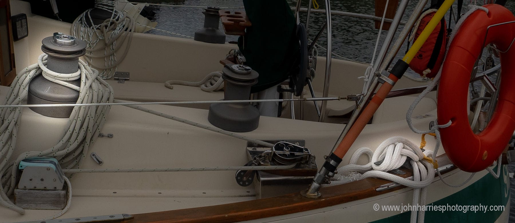
We do have the Bill Copins drogue made here in New Zealand. I have it set up to deploy as Bill and the Pardey’s have recommended: deployed forward, the line led aft through the forward hause, back to the turning block and onto the primary winch. Just like the photo you have on the site of the Valiant 40.
My questions:
Why did this work on Talisen (the Pardey’s boat), a woody; so well, with the enormous loading you have been describing ? Has any consideration been given to the stretch of the 8 plaited line and the 100 meter length deployed? It is a substantial ‘rubber band’? How much of the forces at play get mitigated by the stretch? Or am I on a completely different subject? Are you guys conversing on something else entirely? The photo of the Valiant 40 on your site looks like the line is led forward from the winch via the turning block, so I assume you meant that this was the configuration at risk to failure from excessive loading…. on a Valiant 40?
We have practiced deploying the drogue in moderate winds as Bill Copins recommends but lucky for us, we have not ever really needed to actually use it.
Lastly, I have recently read John Kretchmers’s, ‘Sailing a serious ocean’…. I like the way he describes ‘fore-reaching’ in heavy weather. Makes a lot of sense to me and I am re-thinking the Pardey tactics. Has anybody else considered getting rid of the drogue kit and focusing on keeping control of the boat in heavy going by fore-reaching with storm sail/shortened sail?
Thanks you guys for any help or opinions that you may have, based on ACTUAL EXPERIENCES IN SERIOUS CONDITIONS….. what has worked and what hasn’t…..
Cheers
Hi Devon,
I have discussed all of the issues and other alternatives (including Fore Reaching and the Pardey Bridle) in this online book. I also look at why it’s worth carrying a JSD even though I, like you, have voyaged for 40 years without using one in anger. There are also four chapters of real world experience, as well as numerous asides in said book: https://www.morganscloud.com/category/storm-tactics/online-book-heavy-weather/
Phyllis and I have just completed a full edit on the book, so it’s really succinct and will only take you an hour or two to read.
Thanks John…. Since I have posted I did what I should have done 1st: read into what you have already written on the subject and also the Coast Guard data….. I now understand exactly the point you were making: The series drogue is simply the most effective, easy, passive way of trying to manage a survival situation with breaking seas……….. because the boat is travelling with the water/wave, but slightly slowed by the drogue’s drag, hopefully preventing a roll over/pitchpole. Did I get this right????
Sorry to you and the other readers who have had to endure my ill informed comments/blunder.
I am still new to the site and have not taken the time to navigate through all the copious info you and the readership have contributed…..very sorry.
All that said, hopefully I’ll never be in the predicament where I need a drogue ….. in the meantime, must find someone to buy my never used, new Coppins drogue and look into replacing it with a Jordan Series unit………
Thanks again…. All the best!
Hi Devon, such an honest response – good on ya! Don’t feel bad – I went down the same rabbit hole as you two years ago and know it can be a confusing decision. For us the dilemma was exacerbated by the experience and testimony of our superb NZ Yachting safety inspector who we were working with to get Cat 1. As an experienced skipper, racer and professional engineer he believed his Coppins sea parachute anchor was best in class (due to it’s unique shape I believe that causes the parachute to expand under load rather than contract as most others) and he strongly advocated for us to get one.
Why? He had used his to save his boat and crew when caught in the Humboldt current and a severe frontal passage event with 24 hours of “horrendous” boat breaking waves. He deployed it conventionally over the bow and it kept their yacht safely into the wind and seas, a boat that had been twice round the world. So I don’t think you will have any problem selling your Coppins para – great product.
For ourselves, having read John’s on-line book we decided the risk to our spade rudder was too great to consider a bow deployed drogue / sea anchor or indeed a Pardey bridle arrangement. So we bought a JSD from ACE sailmakers who were great to deal with and then fitted custom chain plates on our strongly built production yacht. No regrets.
Best regards,
Rob
Hi Deven,
Don’t feel bad, I went through exactly the same process and actually used other methods long after Don Jordan had done his work to show that said methods were intrinsically flawed.
And let’s not even talk about how wrong I was about POB prevention and how long it took me to see the simple facts of drag risk staring me in the face.
Thus is the value of this site revealed…even to its owners. There are few people doing this sort of cruising and little opportunity to discuss, never mind evaluate, workable and proven techniques from real sailors in adverse conditions. The only way to escape a rabbit hole is to see the light at the end of the tunnel.
Good discussion.
I am a mechanical engineer, but would not sell my services for calculations on this issue. If you hire an engineer make sure he/she is experienced in assessing strength of comparable structures. Only a few percent are
That said, I calculate that the 14″ cleats on our Passoa 47 are adequate for Jordan’s loads I suspect this is true for most of other well built aluminium boats with welded cleats.
This type of calculation is much simpler for metal boats that for fibreglass ones
Hi Neil,
One of the things I admire about professional engineers is that, by and large, they are comfortable saying “I don’t know”.
I installed two chainplates along each side of my Morgan 382, about 3 feet from the stern. The plates are 1/4″ stainless, bolted through my hull deck joint with 6 3/8″ stainless bolts. As backing, I installed 1/2″ plywood, 1/2″ glass reinforced plastic and 1/8″ aluminum, all longer and wider than the chainplate. With my estimated cruising trim of 21,000 lbs, it fit the Ace Sails suggestions. In worst case, they estimate about 14,000 lbs load on my drogue. If that were all on one side, that would be a massive load. If divided in two, it would be more reasonable. the hull deck joint is two overlapping fiberglass layers that are probably only 5/16″ thick each. If the load is mostly pulling back astern, I think I am okay. If the load was pulling mostly down, the stress on the hull deck joint would worry me. But, this was the best I could do without rebuilding the boat, which, in any case, has a cored hull, so putting the plates along the side of the hull was out. If my computer adept son can figure out how to post pictures here, I will do so. If not, I will just email a picture to John and Phyllis. Anyway, I am not going to take my Morgan into the high latitudes. Although she serves us well, she wasn’t built for the punishment of the roaring 40s.
Hi Terry,
Thanks very much for the details of your installation. Yes, please send the pics along. Also the instructions for posting images are here: https://www.morganscloud.com/2013/11/10/aac-comment-guide-lines/
Here is the drogue chainplate on our Morgan 382, described in a previous post.
https://imgur.com/a/TinWtxT
JORDAN SERIES DROGUE ATTACHMENT
John,
I fully appreciate, and agree with, your position on fabricating proper chain plates for attaching a JSD to a boat. Here in East Africa we are not currently in a position (time or location) to have a proper set of chain plates fabricated before we work our way south down to the Cape and along the Skeleton Coast to Namibia. The last time I came this way (thirty years ago), I depended on luck and good weather reports to keep me out of the soup. At 72 years-old I am now a bit more cautious, and would like the safety valve that a JSD affords.
As a Navy Salvage & Diving officer, I was often tasked to conduct ocean tows of vessels (usually barges or floating dry docks) which had questionable attachment points. We never had formal engineering support or instrumentation to make a determination of adequate structural strength, and often we had to accept the tows on a calculated risk – after backing-up the towing pad-eyes to the best of our ability. We usually assumed that the original design was adequate, and then we had to determine (usually by visual examination inside the rake end of the barge, after sounding the area with a heavy hammer to knock off loose rust and scale) if we needed to augment the towing bridle attachment points. If this was required (in the judgement of the Captain and the Bosun), then the towing pad eyes were backed-up with chain or wire rope to the mooring bitts, and sometimes down the side to a second set of mooring bitts. I realize that this is not the type of sophisticated engineering analysis explained in the comments above, but I never lost a tow.
I am considering using a High-Modulus line attached to three serial points on the deck to create a temporary JSD attachment point to each side of TIGER LILLY: The vessel is a CSY44 displacing about 40,000 pounds. The recommended JSD for a 40,000 pound displacement uses a 7/8″ double-braid Nylon bridle, with the various segments tapering down to 3/4″ and 9/16″. The breaking strength of Samson 7/8″ double-braid Nylon is about 26,300 pounds – my weak-link target strength. Assuming that the vessel yaws just before a large wave overtakes us, a single leg of the bridle (strongest section) may have to carry that full weight before it parts. TIGER LILLY has a utility arch mounted aft with the main bows constructed of 2″ 316L SS heavy-wall tubing (.083 wall thickness), welded to 1/4″ 316L SS deck plates, bolted through the 5/8″ thick solid FG laminate, with 1/4″ aluminium backing plates (rounded corners) below the deck. The aft 2″” bow is welded to a 4″X10″ deck plate fastened with six 5/16″ SS machine screws, which is just inside of the stern hull/deck joint. The forward 2″ bow is welded to a 4″ diameter deck plate, and fastened in a manner similar to the aft bow with six 5/16″ SS machine screws along the side hull/deck joint. The jib sheet winches are ANDERSEN 52ST mounted to the cockpit coaming with a 1/4″ aluminium backing plate and six 5/26″ SS machine screws. I am considering using SAMSON TECH-12 TECHNORA 1/2″ High-Modulus line to connect to each bridle leg of the JSD. 1/2″ TECH-12 line is listed as having a minimum breaking strength of 29,700 pounds, with 30,000 pounds listed as the average breaking strength. As the TECH-12 came aboard from the bridle eye it would take three round turns on the aft 2″ Utility Arch bow (large base in the corner of the deck), run forward to the forward 2″ Utility Arch bow and take two more round turns (smaller round base), and then terminate on the jib sheet winch with four turns and a tug-boat hitch. The three structural elements are nearly in a straight line, with a total of eighteen 5/16″ bolts securing them to solid 5/8″ thick FG laminate. I am looking to progressively dissipate the strain as the TECH-12 comes forward to the winch termination, and to spread the pressure to three different areas of the deck. As near as I can tell from a Google search, a 5/16″ machine screw has about 4,000 pounds of shear strength; but I doubt that all eighteen (in each leg) could be brought to bear equally. I believe that this attachment system would exceed the breaking strength of the strongest leg of the JSD.
OK, that is my proposed plan for a Poor Man’s temporary JSD attachment point that would (hopefully) exceed, and hold, the breaking strength of the JSD 7/8″ Nylon bridle legs. I would appreciate it some of the engineers who read AAC would comment on my plan. In particular I would like to hear opinions on how many round turns should be taken on each of the 2″ utility arch bows. As an old Oklahoma oil field hand once told me, “Tom, this is not the Space Shuttle – we just have to make it work!”
Thanks,
Tom
S/V Tiger Lilly
Tanga, Tanzania, East Africa
Hi Tom,
Sorry, the load sharing, or not, issues here are way beyond my engineering pay grade. I just don’t have an opinion one way or another.
Hi Tom.
I’m no engineer, so I’ll not go into dimensions etc but just a few words, with inspiration from the “just make it work” mind set. With rope passing between different attachment points, close to deck and others structures, and angles changing continuously, I imagine chafe might be the main issue with your plan. High tech fibres are incredibly resistant to chafe, but eventually they do get damaged.
The other problem I see is what you focus on: How to reliably share the load between the attachment points. I think it’s close to impossible to get useful load sharing between points by adjusting the ropes etc. I think the load sharing needs to be self adjusting. There might be other options too, but my only idea would be to pick the two best suited attachment items on one side of the boat. They can be aligned, or not. Then make a loop of high tech rope around both items. You could make the loop long enough to make two complete rounds before you join the ends to make a loop. I would not do more than two rounds, as that would risk uneven load sharing. Let the loop have a lot of of slack, especially if the attachment points are far from aligned.
Attach one JSD bridle leg to the loop, between the two attachment points, around both sides of the loop, around 4 loop ropes if the loop is double. Make sure that the bridle can move on the loop and the loop ropes can move individually everywhere. This system will constantly adjust itself to balance load evenly between all components. The slippery nature of high tech rope helps.
This system with ropes will probably look a bit messy and not be as easy to assemble, as well as relying on attachment points that are not confirmed to be strong enough, so I’d look for a way to make chain plates, when that’s doable, but I do think that on many boats it could be possible to make a strong enough system this way. However, as mentioned, I’d be nervous about chafe.
Stein,
Your loop idea is food for thought…
The chafe issue is certainly germane. My initial plan is to use straps vertically around the TECH-12 to give it a clear path when under strain and keep it up and clear of the deck and cleats.
Another question that has crossed my mind is how strong is a welded joint between the 2″ 316L heavy-wall tube and the 1/4″ 316L deck plate?
Thanks for your input.
Tom
An option I don’t see discussed here and am curious about is installation of dedicated pad-eyes on the transom. This option was brought up by a naval engineer after I had given him my plan for stern chainplates to review. Two separate engineers both told me that bending moment is a concern when using stern chainplates for a JSD. Sufficiently strong pad-eyes are apparently better equipped to handle off-axis loads, provided that a sufficient backing plate is also involved. (I’ve checked, and there is indeed a pad-eye available that will handle the necessary JSD design load for my vessel.)
Does anyone here have experience with or heard of pad-eyes for JSD attachment? I like the idea that the bolts will see tensile rather than shear load. However, my vessel is fiberglass and while stoutly built I’m not so convinced about putting these kinds of loads on the transom, the transom-to-hull corner transition, and along the “thin axis” of the glass. To be honest the primary reason I’m thinking about this option at all is because access to the stern corner on one side is severely hampered which would make installation of pad-eyes harder to get wrong.
Best,
Chuck
Hi Chuck,
I suspect the reason that Don Jordan recommended chain plates is exactly as you say: the fear of putting that kind of load on the transom of the boat. https://www.jordanseriesdrogue.com/D_5.htm
I can see why you like the pad eye, but there is no way I would want to put that kind of load in-effect pulling the transom off the boat
But, people just want to use cleats… The only testing of mounted cleat strengths that I know of is from BoatUS https://www.boatus.org/findings/16/ . While these are for 6″ cleats, I’m guessing that the strengths of larger cleats increases with the square of their size, or for the mounting bolts, with their cross section or the square of their diameter. In either case that would make an 10″ cleat with corresponding larger fasteners 280% stronger. There is still the strength of what they are mounted to to consider.
Has anyone else tested cleats?
Hi William,
I haven’t tested cleats with JSD, but through the years I’ve ripped out enough cleats and jammers to trust them about as much as a guy who just stole my wallet. 🙂 I’d say that if “people want to use jammers”, they should focus on the musical version. 😀
Chain plates ensure that all loads are radial, along the strongest direction. There’s virtually no bending loads. Perfect. Cleats may put the rope close to the deck, (most don’t), but still the alignment of the attachment bolts with the load alignment is poor, which means that big bending loads are generated, exposing both the cleat, bolts and deck area to problems they’re not suitable for.
Sure, anything can be made strong enough, also cleats, but why fight basic physics? If spending enough time and money, it’ll be strong enough, but chain plates would be much cheaper and look less out of place. Any cleat for this purpose is just poor engineering. Why would anyone want poor engineering at a critical safety point on our boat, especially when the right solution is so easy?
Hi William,
Sure a really big cleat may work, but as I point out in the article, do you want to be the one who finds out that, that particular cleat is not up to the job? Point being that there is no practical way to test this other that going out there in a survival storm. The other point is that most existing cleats on production sailboats are no where near strong enough, so one is still on the hook for replacement and reinforcement, so why not just do it right with chain plates?
I’ve been working on synthetic chainplates for our switch to synthetic rigging as the chainplates on our Rival 38cc are a bit feeble and causing some deck cracking. There are now a number of soft padeyes available and I’ve looked particularly at the examples from Colligo.
Now I’ve realised there is potential for using a variation for a JSD.
I’m thinking of a solution that has a “cascade” from the bridle end (using a combination of eye splices and low friction rings) so that you end up with 4 attachment points per side of the boat. Each point has a full backing plate and the cascade ensures that all the attachment points are equally loaded (solving the issue you found with the bolt loadings).
In our case we can have the 4 lines coming through the bulwark (which incorporates the hull/deck joint). We can spread them out longer than would be practical with a stainless steel chainplate and each can have a G10 backing plate properly fitted with thickened epoxy. I’d angle the holes and line them with HDPE tube to reduce chafe further.
The whole lot can be wrapped in a subrella sleeve to keep it tidy and protected before use.
Inspection is easy, as is replacement of any parts even while at sea.
Obviously the key risk is chafe but with careful positioning and chafe sleeves should be manageable.
As far as calculations are concerned the various breaking strengths are documented and tests available. It is much simpler to oversize without significant weight or cost penalty. Plus because of the load balancing there is more flexibility about the positioning to suit your design and construction.
A bit more thinking overnight has come up with a simpler solution.
If your bulwarks are strong enough to be used for chainplates (with appropriate backing plates) . Have a length of Dyneema with an eye splice at each end, with chafe protection sleeves. Create smooth scupper drains. A loop comes through the drain and a stainless steel round bar is inserted through the eye splice. The other end goes through the eye at the end of the bridle and then through another scupper, also with a round bar through it.
The inner side of the bulwark needs to have been prepared with something like thickened epoxy so that the whole length (and width) of the bars is supported (and so that they can’t slide sideways.
The size and length of the bars used in this way as “backing “plates” will depend on the curve and strength of the bulwark.
With weaker bulwarks (or toe rails) you could split the load across more lines & scuppers. This could also be a choice to give a backup if any line should be damaged by chafe.
Sizing the lines so the breaking strain matches the displacement of the boat will give plenty of margin.
Many variations are possible. This one has the advantage of being easily removed when not on passage to reduce risk of damage and allowing full inspection before every passage.
Hi Dave,
Sounds interesting, but aren’t you making a huge assumption about the strength of the toe rail? I know you mention that, but I think it would be a challenge to know one way or the other. Also I would worry about the ss bars distorting and point loading.
Well I’m saying it needs checking, in the case of a Rival like ours the bulwark is pretty much the strongest part of the hull and deck as it is the combined thickness of the two.
Hi Dave
Very innovative.
But for me the worry with these kinds of innovative solutions is what the unintended consequences might be. The point being that chain plates into fibreglass have been in use for decades so we have a huge experience base that we don’t have with this kind of thing. When engineers make this kind of fundamental change to say a car—my nephew works in car engineering—they build test rigs and do full lifetime testing before incorporating it in a production car, even though they have modelled it every which way in the computer. The reason is that the consequences of missing something can be so horrible.
So, if it were me, I would beef up the glass work and use chainplates and wire rigging.
I just don’t want to be doing innovation on a cruising boat. At the very least before adopting something like this I want to see a long term track recored on offshore racing boats, and to date, I have not seen anything like that.
More here:
https://www.morganscloud.com/2016/11/22/the-unknown-unknowns/
https://www.morganscloud.com/2013/10/25/want-to-get-out-cruising-dont-be-a-pioneer/
Yep, thing is with our 43 year old Rival there is plenty of experience in the Association that the original isn’t that great. For all but the Cap shrouds all we have is essentially a bronze eye bolt through the side deck with two thin rectangles of stainless plate as backing plates. Where the two plates have become mins-aligned the deck has cracked. The Cap shrouds have an extra connecting piece that is bolted to the bulkhead.
They are custom bronze fittings and are not long enough for beefier backing plates. So we are confident we need something different.
As a ketch (no triatic) we are able to do the mizzen first. Also we will be able to test for a few years before crossing oceans.
So this level of innovation is within our comfort zone.
We see lots of boats around the 40 year mark needing to replace chainplates. So the original designs were not always good enough, replacing something that has failed with the same doesn’t seem that risk averse ?
Hi Dave,
I did not suggest replacing it with the same, rather I said beef it up and use a chain plate. There are a bunch of ways to do that, that are tried and proven.
Yes, there are. But given we are choosing synthetic rigging we would end up with a lot of expense for custom stainless steel work that would still need extra fittings to attach the synthetic rigging to. This way we get a high quality closed stainless thimble that is part of the synthetic “chainplate” ready for the lashing to the shroud. Below we can fit a FR4 backing plate bonded to the underside of the deck and with a knee to another FR4 plate bonded to the hull. All things we can visually inspect plus we can have spares and tools on board for any repairs.
Absolutely not for everyone but we have been through it with experts and are confident enough to first test with our mizzen.
As for synthetic rigging both Colligo and a someone in Australia (can’t remember the name, he has been doing the work for Free Range Sailing YouTube channel) have been doing it for many years (the Australian for more than 10 including boats that have circumnavigated). So while it has been rare it isn’t new or unknown.
I’m not suggesting it for you ? but it is within our comfort zone. Here it was relevant only as a idea for us to apply to the JSD attachment.
In the article above you say:
“And, further, I’m fairly sure that most cleats are cast, and while I’m no metals expert, my guess is that a cast item is intrinsically less reliable and more prone to strength-robbing manufacturing defects than a chainplate cut from plate stainless steel or aluminum. (If any of you engineers out there have insight on this, please leave a comment.)”
I’ve read through a number of the comments below that talk towards this and would just like to add a bit. The question above asks, seems to me, if there is an inherently greater reliability of a wrought alloy versus a cast alloy. Really, the answer is – it depends. There can be differences, it does depend upon the alloy, and it also depends upon all of the manufacturing processes the part is subjected to. Given the complexity of the system under discussion, there are many other aspects of greater consequence than if the material is made from a cast alloy or a wrought alloy. The specific alloy chosen is of greater consequence than if it’s cast or wrought. For example, if I had a cast 17-4 PH stainless steel cleat versus a wrought 17-4 PH stainless steel cleat it would make no difference to me or to the performance of the cleat. As long as both were manufactured correctly. Those “correct” manufacturing processes – while essentially the same alloy – are different for the cast alloy vs the wrought alloy. Every specific alloy would have it’s own requirements. But really, the question of cast vs wrought w.r.t. reliability is not the issue.
Hi David
Sounds good. As I said, I’m no expert. The key point remains though: there is no way for us to know for sure that the cleat is up to the job.