A few days ago we covered the shape and type of keel that the Adventure 40 will have. Now let’s move on to the strength and grounding resistance of the keel.
The Grounding Problem
Why does this matter so much?
As some wag said:
Cruisers are divided into two groups, those who have run aground, and those who lie about it.
The point being that most all of us will run aground sooner or later. But that shouldn’t be a cruise ender. Sadly, though, in many, probably most modern production cruising boats, unless we are going very slowly, it will be.
How slowly?
The 3-Knot Rule
Maxime, who is in charge of making the Adventure 40 real, has an extensive background and contacts in the French sail-training world where boats get run aground all the time.
The experts in that world tell him, based on bitter experience, that most modern production sailboats are likely to sustain some damage, requiring repairs, in any grounding on a hard object at over about 3 knots.
And in many cases, particularly if the speed of impact is over three knots, the damage will be extensive.
Not good, given that most any decent design will be doing at least that speed with the engine idling in forward gear and probably at least 5 knots under sail, and are we really going to run at 3 knots or less every time we’re near the hard stuff? Not likely.
Difficult and Expensive
So what do these “extensive repairs” look like?
Difficult
With modern construction techniques that often consist of dropping a reinforcing grid into the boat on top of putty, and then not even passing the keel bolts through said structure, but only through the skin, the damage modalities are very difficult to repair.
For example, a really good repair will usually require removing much of the interior cabinetry to get at the grid, and then days of grinding and expert glassing, followed by reassembling the boat.
Expensive
It’s hard to see how any yard, no matter how efficient, could take this on for less than US$20,000, and I have seen a full repair of this type that went over US$100,000.
Not Acceptable
Our cruising dreams dashed through a simple mistake that many of us, maybe most, will make sooner or later?
A cruising boat should not be this fragile.
And Dangerous, Too
However, the results of a grounding could be a lot worse than broken cruising dreams. To understand why and how bad this is, let’s look at the Cheeki Rafiki tragedy.
Work done by the investigators, assisted by the Wolfson Unit of Southampton University, in response to the Cheekie Rafiki tragedy, showed it was almost impossible to reliably assess the damage after the groundings the boat experienced, and that this difficulty is intrinsic to the construction methods used on many of today’s cruising boats.
Was that just an isolated incident? No, the danger is built into many production boats:
Wait, it gets worse:
An engineering study commissioned by World Sailing shows that the standards required for keel strength for offshore certification under ISO are inadequate to the point that as little as 5 years of ocean racing or 25 years of moderate cruising can result in fatigue to the point that failure becomes likely, even if the boat has never been grounded—see Further Reading.
Yup, you got it, many modern cruisers are built inadequately from the start, even if certified to go offshore, and are impossible to survey properly for damage.
This situation is so bad that World Sailing recently added regular keel inspection requirements to the newest version (2022-23) of the Offshore Special Regulations. Although, given the difficulty of actually assessing keel integrity in the real world, that’s a band-aid over a gaping wound.
World Sailing are also lobbying ISO to significantly upgrade the keel strength requirements; however, after several years of representations to ISO, it’s still not clear when, or even if, there will be any improvement.
Not Just Theory
This is not just theory. Walk around any boatyard and look at the keels on boats over 10 years old. You will find, as I did, that many, often a majority, are showing signs of movement in the keel-to-hull joint. And once there is movement, fatigue, which is probably already occurring, will be accelerated.
The Adventure 40 Ain’t Waiting
This all sucks, big time, but the Adventure 40 team is not waiting for the regulators to fix this mess.
Maxime has been working on this issue since last year. Here’s a summary of his plan to make the Adventure 40 keel and attachment as close to grounding proof as is practical and strong enough to withstand decades of offshore sailing.
Much Worse With Speed
To understand Maxime’s approach, the first thing we need to grasp is that the impact energy a given structure must survive increases far more than linearly with the speed.
Setting The Goal
That’s scary enough, but Maxime started out with the goal I set of building the Adventure 40 strong enough to withstand a grounding at hull speed without significant damage, and quantified that at 8 knots.
Yes, that’s way faster than any prudent mariner would be traveling around the hard stuff, if for no other reason than that a grounding at that speed could maim the crew, but by using such a high number, in concert with good engineering, we will end up with a structure easily able to forgive more likely mistakes, and also one that will be able to withstand the normal strains of offshore sailing for decades.
In short, setting a high-impact speed goal, combined with good engineering, will yield a keel design with good safety margins regardless of whether or not she is ever run aground.
It’s a Big Challenge
Just how big a challenge has Maxime set himself? Huge. An 8-knot grounding is seven times worse than a 3-knot grounding, all other things being equal.
But just making the boat seven times stronger than most built today is not practical. Way too costly and way too heavy. And, besides, there’s a better way.
A Metaphor That Helps
Think about a glass that drops off a table onto a concrete floor. It breaks. How could we fix that?
One option would be to make the glass really, really thick, but then we would end up with a glass that was impractical to use, and, anyway, the more rigid we make a structure the more vulnerable it becomes to impact forces.
A fundamental here is that to withstand impact force without damage, a structure must stretch, compress and/or bend. Very stiff structures do not absorb shock loads well. Hit a stiff cored hull panel with a hammer to test this…assuming you like expensive experiments.
So a better option is to make the glass a bit thicker and then coat it with a thin covering of rubber. Problem solved.
We Need a Bumper
Same with the Adventure 40. We need a shock absorber as well as building the structure strong.
With that concept firmly in mind, Maxime took the problem to a group of engineering students at CentraleSupélec University, to see if all this could be analyzed, rather than just iterating empirically (a nice way of saying “guessing”) as is often done around boats.
But what material should be used for the shock absorber in the model?
Doing The Numbers
Well, we all know that lead keels deform quite a bit when hitting a rock. Just walk around any boatyard and you’ll see evidence of that.
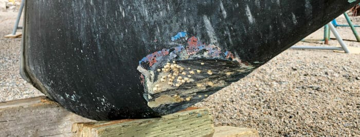
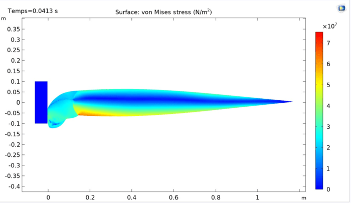
So let’s see what Maxime and the students found when they ran a lead-keeled Adventure 40 onto an immovable rock at 8 knots in the computer:
Yikes, the front of the lead keel deforms a bunch.
But that’s good news, because in so doing the peak forces the whole structure, including the critical keel-to-hull joint where most damage normally occurs, are subjected to, are much reduced because the deceleration from 8 knots to stopped is spread over a longer period of time, as we can see here:

And, better yet, there are no nasty high peaks of deceleration in the above graph. The deceleration of hitting the rock very quickly produces about 6g and then peaks at 8g.
Not trivial, but a heck of a lot less than if the keel was, say, made of cast iron.
The Breakthrough
And this in turn has allowed Maxime and his team to take a very complex dynamic problem and simplify it to arrive at the maximum impact that the entire keel and its attachment to the hull must be engineered to withstand.
Wait, read that again. That last paragraph contains the gold nugget of knowledge that will make the Adventure 40 better.
Here’s why:
Now that Maxime’s team have calculated peak deceleration from modelling, they can derive the forces the entire structure must be engineered to withstand.
So the remaining work is to design the keel bolts and structure to absorb the resulting forces without damage, an engineering problem that the engineers Vincent and his team will work with are eminently qualified through both experience and training to do.
Heck, we are getting this done in the country that engineers and builds Ultime Multihulls and IMOCA 60s, so getting the engineering right to achieve this goal for the A40 should be doable!
That said, that simplification should not lead any of us to undervalue the work that Maxime and the students have already done. None of the presently used construction standards make even an attempt to quantify and plan for the dynamic forces in a grounding.
And, better yet, a keel engineered to withstand these extreme grounding forces will be many times stronger than that presently required by ISO and/or than required to withstand normal sailing loads.
Not Perfect
So does this mean that engineering the Adventure 40 keel and attachment to withstand an 8-knot grounding onto a hard rock is a solved problem? No, not completely.
First off, to arrive at optimal shock absorber characteristics:
- hard enough not to be destroyed by the impact before slowing the boat, but
- soft enough to extend the time it takes for the boat to stop;
the students modelled with pure lead, rather than a lead and antimony alloy, as is usual in the manufacturing of keels.
So the question now becomes, is it possible to build a keel out of hardened lead but with a pure lead bumper at the leading edge? Yes, it’s a challenge, but I for one am betting it’s solvable.
How Much Certainty?
The other thing we need to think about is the accuracy limitations of the modelling done to date, as well as changes in the assumed scenario that will produce higher forces; for example, changing the shape and/or impact point of the rock—there are a lot of variables here.
Realistically, all of this means that the builder will never be able to honestly say, “Run an Adventure 40 aground on a hard rock at 8 knots and everything will be fine every time” (except for bruising of the keel and probable injuries to the crew).
In fact, the 8-knot no-damage target speed may have to be reduced if we find that building the structure to withstand the forces, even with the lead bumper, is impractical. Rest assured, however, that said safe speed will be way more than 3 knots.
But what the builder will be able to say is, “The Adventure 40 will forgive the typical grounding mistakes made by a seamanlike owner and will survive decades of offshore voyaging without dangerous strength deterioration”.
Way Better
That’s a huge step forward when compared to most of the production sailboats available out there today, about which most-everyone just sticks their heads up their…in the sand…rather than even thinking about the likely outcome of a grounding or what condition the keel-to-hull joint will be in after even just 10 years of hard offshore voyaging.
Fix In The Field
Of course, all that leads to another obvious issue: what happens after we have hit the rock and mashed up the front of the keel as shown in the first graphic?
Clearly, we need to think about the way that owners can fix or replace the soft lead bumper in the field.
But let’s not forget that being in, say, Newfoundland with a huge bruise on the front of the keel after a grounding, beats hell out of being in a normal production boat in the same situation with the reinforcing web that all the interior furniture is attached to separated from the hull, and the aft end of the keel driven up into the hull causing a crack that’s letting water gush into the boat.
We can easily sail the Adventure 40 with a mushed forward part of the keel to a yard to haul. And, better yet, the repair is all outside the boat and should be doable while we live aboard—you are not a real cruiser until you have lived aboard for a couple of weeks on the hard.
Worst case we can chisel off the deformed lead—no, it won’t be fun, but it’s doable with normal tools—and fill the divot with epoxy putty. Good enough to continue the cruise or sail the boat to a well-equipped yard for a better repair.
An infinitely better situation than that on a typical modern production boat where our cruise is over and we are faced with a huge repair that will take a well-equipped high-end boatyard with highly-skilled composite technicians months to complete at a cost that could exceed the value of the boat…assuming the boat didn’t sink under us.
The Cherry On Top
And here’s the cherry on top of this analysis. So far it looks like we will end up with a lead keel, which is by far the best option for a cruiser, since lead does not rust and is heavier than iron or steel for a given volume.
Isn’t it ironic that after all this high-tech analysis we end up with the ballast material that we cruisers have known intuitive for decades was best?
This also makes me wonder how much of the increase in grounding damage and failed keels should be laid at the door of the cost-driven change to cast iron and steel keels, that started in the eighties, since these materials are far less ductile and, therefore, impose far higher forces on the boat in a grounding.
All that said, to get the strength and longevity we want it may be necessary to use some steel and/or cast iron in the structure. The point being that we don’t want to tie Maxime and Vincent’s hands while they are engineering the best possible solution.
One More Thing
Given that it now seems likely that the Adventure 40 will have a lead keel, I will—I have not mentioned this to Maxime yet…surprise, surprise, surprise—lobby hard for bronze keel bolts.
My reasoning being that a properly engineered and built lead keel with bronze keel bolts is pretty much a forever-keel (see Further Reading), which is in keeping with a core Adventure 40 principle:
We are building a boat that, with reasonable maintenance, will safely take people voyaging for decades to come.
And, yes, using lead and bronze will undoubtably make the boat more expensive than a steel, or iron, keel with steel bolts, but the benefits in cost of ownership over time, as well as resale value, will far outweigh that.
Summary
So after two articles, here’s what the Adventure 40 keel looks like:
- External bolted-on fin keel.
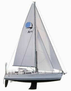
- Modern shape with a bulb for performance and better load-carrying capability.
- 6.5′ (2 m) draft.
- Likely made of lead.
- But possibly with some steel.
- With bronze keel bolts if all lead…if I get my way.
- Capable of withstanding the grounding impacts that a seamanlike owner may subject the boat to, with only damage that’s external and relatively easy to repair when out cruising.
- With a keel-to-hull joint many times stronger than modern practice or current offshore standards require.
Or, to put it more simply, a real offshore cruising boat keel designed, engineered and built to be fit for task in the real world. It’s the Adventure 40 way.
Maxime’s Paper
In the interests of brevity I have summarized the living hell out of Maxime’s work, leaving out a lot of really interesting stuff. And I could easily have made a mistake. So if something is wrong in the above, it’s almost certainly my fault, not his.
Anyway, I highly recommend reading his original paper. See Further Reading. I found it fascinating and much easier to understand, even though I have no engineering training, than I expected.
Maxime’s ability to explain complex engineering in simple terms is amazing. Doubly amazing when we remember that English is not his first language—bodes well for the future of the Adventure 40 with him in charge.
Further Reading
On keels:
- More detail on the current state of keel strength and longevity
- On keel bolts and how difficult it is to assess condition
- How much replacing keel bolts will suck
- Why an encapsulated keel is not the answer
Supporting papers:
- Maxime’s excellent paper
- If you want to understand a bit more about the physics at work here, this video helped me a lot
- My assessment of the Cheekie Rafiki tragedy with links to the enquiry and analysis by the Wolfson Unit
- An article by Matt Marsh on why fatigue skyrockets when we take a boat offshore
- Study by World Sailing². The really scary conclusion is on page 23, screen shot below:
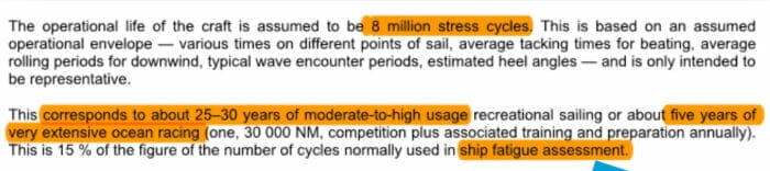
²The study focuses on high-performance race boat keels built of welded steel structures, so some would argue that it’s not relevant to the boats we sail. I don’t agree. The ISO rules are not scantling rules that specify how a boat is to be put together, but rather rules that specify what forces and usage the boat must be able to withstand. So if said rules allow a boat to be built and certified as fit to go offshore with a keel that can drop off due to fatigue alone, with no groundings taken into account, after just five years of hard racing, or 25 years of cruising, surely we should not be trusting our loved ones to the same regulation regardless of how the keel is built? Fibreglass structures are subject to fatigue, too.
Comments
If you have questions, please leave a comment. The answer may be way past my pay grade, but Maxime will be here.
If you see an error in my interpretation of Maxime’s paper, let me know, but read Maxime’s paper first to make sure it’s not just my effort to simplify that’s bothering you.
Also, if any of you engineers who comment here at AAC have corrections or suggestions for improvement, Maxime and I are all ears, although do keep in mind that it’s early days yet and much more engineering work will be done by Maxime, Vincent, and the team in the weeks and months ahead.
Does the bumper need to be fwd of the fin leading edge to work?
(not an expert) the bumper material would need to cover the front and bottom of the keel
Hi Adam,
The bumper does not need to cover the entire bottom of the keel, but just the lower part of the bumper area. The only reason to cover the entire bottom of the keel would be if we were trying to guard against the boat being repeatedly dropped by swell on a rock. And building a boat that can withstand that is not practical. That said, by having a lead keel and substantial keel to hull joint, the boat will be way more resistant to that treatment than most any boat being built today.
See Maxime’s paper for more detail on that.
Hi P D,
See Maxime’s paper for more on that. Short answer, yes, shape and position of the bumper matters, but that will not result in a protruding area to catch fishing gear etc.
At X-yachts they use a galvanized metal frame to support the keel. I am sure not new to most readers but maybe interesting for Maxime and team to consider.
https://www.youtube.com/watch?v=zshhHdxipzs
Hi René,
Good point, and Nautor Swan used to do the same. Certainly one option for building a strong joint that I’m sure the French team will consider.
Yes, I can’t think of a better way to distribute the massive loads from the keel, to the hull, than through a large steel frame bolted to structural bulkheads and stringers in the hull. It also has the added benefit of being an excellent mast step base.
I believe a bonded carbon frame would be too brittle to survive a hard grounding.
There are many performance yachts using this design in Europe today. X-Yachts, Arcona Yachts and Solona Yachts, just to name a few. The latter even ties in the chain plates to the steel girder.
Hi Timothy,
thank you for your input!
I definitely agree that the metal frame is a valid solution that we will consider – but it’s not the only one: composite too, as long as properly built, can do the same (let’s remember that the core structure of the A350 is mainly composite materials, albeit with many bits of metal!). In any case, for us, there won’t be carbon fiber in the main structure – and at the very least, the composite structure will be in charge of holding the stay and backstay tightly!
Hi Maxime,
That makes sense. I remember that Matt wrote an interesting article on the difficulties and dangers of mixing different materials with different strength and stiffness characteristics: https://marine.marsh-design.com/content/do-fibreglass-and-carbon-fibre-mix
He was specifically writing about mixing carbon and fibreglass, but I can see that mixing metals with composites might have many of the same challenges.
And given that we need to dissipate deceleration over time to reduce load peaks, as I learned from your excellent paper, perhaps it will turn out that an all composite solution is the best combination of strength and impact resistance particularly now that we have so many options for different cloths such as unidirectional, bi-axial, etc that engineers can use along load paths to come up with a strong solution without adding unnecessary weight.
Anyway, this is the domain of you engineers, not old yachties, like me.
Talking of which, I do wonder whether X-yacht stick with the metal backbone not because it’s the best engineering decision, but because it’s part of their brand and sounds strong to us lay people.
I used to race on a X-yacht 435 (deep draft, L-keel, built in ~’90 as I recall). About 10 years ago, as we motored out of the harbor, the boat’s keel hit a dredge pipe. Our speed was about 4 kts, no more than 5. It was quite a jolt! We definitely felt a hard pitch forward, as expected and described in Maxime’s paper. After the race, the owner had the boat hauled for inspection and no more serious damage than lead bulb deformation was found! The boat is still actively raced and her skipper is planning to sail her to Hawaii.
Without a doubt the only way to go. Why reinvent the wheel when X-Yacht figured it out many decades ago. They also have an epoxy resin, oven cured hull with a gelcoat finish. I really hope all of the above can be incorporated into the Adventure 40.
What a perfect boat that would be!
John interesting idea and I have some real world experience. I used to sail regularly a Contessa 34, for a sailing school, that had a lead keel. The Contessa 34 pre dates the grid designs and the keel was bolted to the bottom of the hull, with the usual arrangements of stringers and ribs to stiffen the hull.
Another skipper sailed the boat onto a rocky lee shore at night in strong winds. The resultant repair was significant and the the hull had additional stiffeners inside added and the forward part of the hull where the keel flange is bolted against, dressed and more GRP layers added. The point here is that the hull is likely to have been stronger than originally designed after the repairs. It should be noted that the boat sailed about 20 miles after the grounding, to a repair yard, so obviously no significant leakage if any.
A few years later, many, many more miles under the boats belt, I am skippering her. High water springs, I cut a corner of a small promontory into a bay. Motoring at about 5 or 6 kts I struck the bottom hard and bounced over the promontory. Inspection revealed no leaking.
I delivered the boat over 60 miles back to base where the yacht was lifted. A mash about the size of 4 x fists was visible in the toe of the keel, with the lead mushroomed out. After inspection by surveyor, there was no noted damage to the GRP. The yard reshaped the toe of the keel and the boat was launched and sailed onwards.
I also have anecdotal evidence of a custom racing yacht (not a cruiser racer), lead keel, that I witnessed strike a rock under spinnaker at speed. I saw that yacht lifted, again the keel was mashed badly at the toe, but she had received damage to her structure. All was repaired and the yacht raced competitively for years. Again this yacht predated grids. Both examples happened mid 1980’s.
Last example, Sigma 41, owner motored over a rock at about 7kts , partly split the keel from the keel flange, with a significant laminar tear, damaged stringers but no leakage. Furniture removed, GRP repaired, thickened and stiffened, new stringers and ribs added, new keel bolted on. Again predated grids.
I think my example shows that lead tipped keels, and strong hulls can be a good solution for a grounding resistant design.
Hi Alastair,
Very good information, thank you. And I agree that those incidents and many others that I have witnessed back in the day show clearly that a bolt on lead keel can be done right and be very robust. The problem is that since the advent of poorly built grids and iron keels younger sailors without the kind of experience you relate, and I remember, have come to the erroneous conclusion that there is something intrinsically wrong with bolt on keels, when in fact the problem is construction techniques that started in the eighties. We have a LOT of education to do on this one.
There’s nothing intrinsically wrong with bolting a keel onto the outside of a hull.
The problem comes when you bolt one onto a structure that is neither rigid enough nor strong enough to carry that kind of load.
I am quite certain that I, or anyone else familiar with the problem, could design and build a bolted-on keel and hull structure with an expected lifespan of well over 200 years, just as I am quite certain that I could design and build one that’d be likely to kill the entire crew within hours of leaving port.
Hi Mal,
Yes, I’m aware of that sad situation and have watched a bit of the video. But it’s important not to confuse horrendously poor design, engineering, and construction with an intrinsic problem with bolt on keels. Based on my own experience and that of many others who were cruising back in the day, done right, bolt on keels are by far the most robust option for a cruising boat and also give us a big performance and load carrying advantage over encapsulated. It’s little known today, but encapsulated keels on fibreglass boats came to be not because they were better than bolt on lead, but because they were cheaper and easier to build.
See the link in further reading and also Alastair’s comment further up this thread.
Hi John,
This is interesting info and all makes sense.
I just wanted to mention here that this is a very important issue. Boats loose keels way more often than we think. I have no way of quantifying it, but we hear about the high profile cases like Cheeky Rafiki and the big Oyster off Portugal or Spain. However, most cases seem to be not reported, and luckily many of them seem to go without the boat flipping over.
One documented story is the charter sailboat that operated from Portsmouth or so, sailed to Isles of Scilly, ran aground and lost the keel. It spent more time there and went back to the home harbour, mostly motoring. Then it was discovered that the keel was missing. They later found it on the bottom where the grounding had happened.
Another charter company I had a skipper job for 4 years ago, based in Corfu Greece, claimed that they had a boat losing its keel every second or third year. None had capsized yet. They have about 60 boats. Most renters there are completely inexperienced and run by motor most of the time, as the wind is mostly very light in the summer.
Privately owned boats get way better treatment, of course, but this does indicate that the focus on a strong keel system is good thinking!
There are a surprising number of modern, wide-beam, wide-transom boats, of the kind favoured by bareboat charter firms, that can lose their keels without capsizing or sinking. I gather that it is, indeed, not uncommon.
Those hull forms will, in ordinary light-wind use, only use the keel as a foil; their sail-carrying power comes from their width and shape, and sailing without a keel might just mean the boat can’t point worth a damn and makes 24° of leeway. The loss of the keel might only become catastrophic at high angles of heel (i.e. an increasing wind / deteriorating conditions).
That certainly doesn’t make it OK to design and build their keel joints so poorly, though!
Hi Stein,
I agree, this is a far worse problem than most cruisers know. I’m on the CCA Safety and Seamanship Committee and we get regularly briefed on the efforts at World Sailing to improve the situation. Sally Lindsay Honey chairperson of the Safety committee at WS has taken on the daunting task of compiling a data base of keel losses. I have seen this list and it’s disturbing!
Very interesting.
Obviously a good thing to have a design that has properly thought through this issue.
The image reminds me that a lot of groundings are onto sandbars with the extra issues beyond the initial impact eg bouncing in a swell and side loadings as the boat dries out.
I’ve read the other articles and am quite content with the encapsulated lead ballast keel on our Rival 38. We know the professional who has epoxy coated the hull. The survey found no moisture, cracks or faults. So far as I know there have been very few issues with any Rivals (the only one I know of was early boats having too little strength around the aft full depth bilge – ours is deep but nothing like as deep as the keel).
The other issue for me is that in search of performance we see few bolt on keels with a hull shape that is designed not to slam. When it comes to beating to safety in bad weather it seems to me that performance of many modern designs is limited by the ability of the boat and crew to endure slamming.
I will be interested to see how the hull shape of the Adventure 40 tackles this comprise between wetted area and slamming with the constraints of a bolt on keel.
Hi Dave,
I have a very hard time seeing any connection between whether or not a boat slams and pounds and whether or not she has a bolt on keel. Based on my experience easy motion is mostly about hull form, not how the keel is attached to the boat. That said, I totally agree that not slamming is a safety issue, and have written about that many times. Anyway, having a hull form that does not slam is, and has always been, a core requirement for the A40: https://www.morganscloud.com/2022/02/13/adventure-40-dimensions-and-hull/
I am pleased to see Maxime taking this seriously, and I believe his initial analysis of the true grounding loads is generally sound and well-reasoned.
The overall approach here, of letting the lead keel deformation dissipate the worst of the impact shock and then carrying the resulting forces and moments up to the keel joint, is a good one. It’s certainly a significant improvement over the ISO standard approach of “this calculation will make it just strong enough to not fall off by itself when the brand-new boat is sideways”.
The cost difference between lead and cast iron is not as significant as is commonly thought. Lead typically varies from $1800 to $2300 per tonne; steel from $500 to $800 per tonne, to which you add tooling, labour, and transportation. 1″ SS316 threaded rod is $50 a foot retail; the same stuff in B98 bronze is $140 a foot. Not negligible, true, but we’re talking about an increment of maybe 1.5% to 2% of the boat’s cost for something that will more than double its safe service life. Unless you have a large and intimidating accountant whispering “BOM Reduction….” in your ear, there’s very little reason to let the base metal commodity cost override the engineering-based decision.
Fatigue and corrosion of the metal keel itself is more of an issue on the ultra-thin, high-aspect-ratio foils used in modern racers. We can safely assume, for the keel shapes common in cruising boats, that the keel itself will be so incredibly strong as to outlive the entire rest of the boat. The joint itself is the problem, specifically:
The usual tendency, if working to “The Standards”, is to design a wonderfully strong and perfectly standards-compliant bolted joint, immediately below a brutally awful fibreglass structure that’s only marginally better than cardboard soaked in cheez-wiz.
Grounding-related damage in fibreglass boats usually seems to come from a failure of the 3rd point, i.e. the bolted joint survives but it tears the inadequate fibreglass structure apart above it.
Grid-debonding and fibreglass-fatiguing failures at the keel joint generally seem to come from a failure of the 4th point, i.e. the hull just above the keel joint flexes on every roll cycle, gradually peeling the grid bond and/or enlarging cracks and fractures in the fibreglass laminate. This problem is greatly amplified when the keel is just bolted to the skin with washers or small plates and the skin is bonded to the grid liner, rather than having the keel bolts pass directly through solid transverse structural members with large backing plates above, as is the proper and correct way.
Thanks Matt for sharing some of the details of the engineering challenge in creating a robust keel to hull joint. It seems logical that a wider longer joint will be far more resilient. By making the keel longer (chord) and shallower (less draft, less leverage on the joint the whole structure gains massive strength and longevity. The trade-off is of course a couple of degrees of pointing ability. We all know boats are full of compromising requirements. This one pulls 4 ways.
Draft
Grounding resistance
Cost
Windward ability.
Just because a boat won’t point high doesn’t mean it can’t be fast. Weather forecasting has never been better. Not many chose a windward passage over reaching and running.
Travel lifts are not available every where, even in developed countries The ability to haul out on a cradle or dry out next to a wall become much safer as the keel (chord) increases.
I would prefer a cheaper (attainable) robust design with shallower draft giving more options for berthage/mooring/anchorages. A design optimised for fast running and reaching rather than pointing a few degrees higher.
Hi Peter,
I hear you on the benefits of shallow draft, but as we discussed in the last article the drawbacks in performance make shallow draft simply not worth it unless we go the whole hog to a lifting keel or centre board boat. Also, 6.5″ is hardly excessive and building a keel that is crash resistant at that draft perfectly attainable with good engineering. (Matt and Erik have already confirmed that.)
Also, interestingly in some common scenarios the crash energy on a shallower draft keel are higher than on a deeper keel. Read Maxime’s paper for more on that.
Hi Again Peter,
I should add that I think relying on weather forecasting to make up for performance inadequacies in a cruising boat is one of the most disturbing trends out there in cruising today and a lot of why so many sailboat cruisers today motor well over half the time. Sailing ability is a core fundamental that differentiates the A40 and just not something we should compromise on. I cover two common scenarios in which the A40’s ability to go upwind and point high will make cruising boat safer and more fun, as well as greener since there will be less temptation to motor: https://www.morganscloud.com/2022/02/13/adventure-40-dimensions-and-hull/
So sure, I can see a place for shallow draft fin keel boats, although not a big one since I prefer lifting keel boats for that function, but that’s just not what we are building here with the A40.
Hi Peter,
just one point to add, that you don’t explicitly mention: a deeper keel will also be lighter. So it’s not only about windward ability, it’s also about light wind ability.
In my view, the trade-off between the 4 goals you mention will more or less boil down to a trade-off between draft and sailing performance. This is because, as discussed in the previous article, this trade-off is of the kind that could be called very “convex”: the additional nuisance of each additional foot in draft is greater than that of the previous foot, and, conversely and even more strongly, each new foot brings much much less in sailing ability than the previous one (especially in harsh weather). So we get large drawbacks as soon as we significantly deviate from the initial trade-off. On the other hand, the engineering challenge won’t change much with each foot. Granted, a shallower keel will impose slightly reduced force moments on the joint – and also slightly stronger direct forces, because at the end it must confer the same righting moment to the boat. As to the costs, we must factor in that the mass of lead decreases as the draft increases…
That said, of course draft and ability to occasionally dry out along a wall matter! I will make sure that we correctly understand all the parameters, before freezing anything.
Modern twin keel designs might present some interesting alternatives for improved damage resistance.
Hi Eric,
I agree that twin keels are interesting and seemed to have enjoyed somewhat of a resurgence in recent times. That said, if they have a long enough span to dry out on they add a lot of wetted surface and drag for a benefit that will only be used occasionally, except for cruisers who have that specific need, which is a niche market.
They will also have to be heavier than a single fin, with the resulting negative effect on payload.
The other problem on a twin keel boat is the rudder. Either one must have two with all the attendant expense, or one in the middle that is not protected by a keel.
So I think they have the same unfavourable performance to benefit ratio as shallow draft fin keels in relationship to the A40 project.
Hi Maxime,
I am glad you mentioned keeping your eye on light wind performance. Too many cruising boats do not lend themselves to an acceptable light air performance. Much of the widely-wandering cruising world’s best locations enjoy light airs and too many cruisers are quick to turn on their engine and never are tempted to learn how to make their boat go in light airs. I learned a lot about keeping a boat moving in light air when we were in the Med and really appreciated that learning in many other areas. And mine is not a design particularly partial to light air although once you get her going in one direction she goes well and keeps on trucking along: which is fine for cruising.
My best, Dick Stevenson, s/v Alchemy
Hi Dick,
I agree. To me one of the biggest myths in cruising boat selection is that of the desirability of low SA/D and that being slow is somehow desirable or more cruisy.
Thanks for your reply Maxime, I agree with you about keeping the boat light in order to benefit light air performance. Too many cruisers overload their boats.
I guess the discussion about draft is relative. My experience with my own boats is sailing between NZ and the Pacific Islands and coastal New Zealand. Current boat which is 40ft LOA 10t. 1.75m draft. Previous yacht was shorter and had less draft again. Both very capable ocean going vessels.
Average speed on passage is better than 6knots and this has always been fast enough to work with the weather windows for a safe, fast passage. I have never demanded better windward performance to achieve my goal. I do motorsail at times, this is a useful tactic to keep the boat moving in light conditions through the centre of a high. Typical fuel burn on a passage is less than 1.5 litres per hour. On a typical 1000Nm passage I will use 100l or less.
I do take notice of the weather but have been known to leave with the wind directly on the nose to make use of the weather coming and particularly to increase the likelihood of favourable conditions on the approach to New Zealand. I’m not waiting endlessly for a down wind sleigh ride, it’s not the trades it’s not going to happen.
Having a draft of less than 1.8m has enabled me to find berthage where otherwise there would have been no availability or only at a much greater price. Hard fact is it’s getting much harder to find a place to leave your yacht.
The only thing I have ever hit was the cradle I was about to be hauled out on. The impact was felt although speed was less than one knot. On examination the lead was quite deformed but very easily repaired by hammer blows to the side and a little dab of epoxy filler. Lead (even with antimony added) is great stuff for keels, I’m not sure it needs to be very much more complicated than that.
There is another factor in grounding survival, which is hull flex. Legendary among J42 owners is an incident years ago S.E. of Vinalhaven, Penobscot Bay, Maine, when, in the course of a race I believe, a J42 doing 7 kts. came to an abrupt full stop, its keel coming up against an uncharted rock ledge. The hull, resin infused balsa core, flexed, dislodging and breaking most of the salon interior cabinetry and woodwork, but the boat survived otherwise unbothered, and is still sailing with rebuilt interior. It’s hard to imagine the effect of a 10 ton boat meeting an immovable object at that speed, but it wasn’t just the lead keel that saved her.
Hi Reed,
That’s a very good point confirming the key point in all of this: something must distort to absorb force.
It seems one can think of this bumper concept somewhat like the “crumple zone” in a modern car unibody/frame. It’s an area that has been engineered to sacrificially absorb impact, moderating the rate at which the vehicle goes from cruising speed to stopped (during a crash or grounding). Thus it reduces the loads transmitted to the critical parts of the vehicle.
In the case of the car, the crumple zone protects the passenger compartment. In the case of the keel, what is protected is the integrity and structure of the hull, in particular the floors that form the critical hull-to-keel connection.
A big difference is that the keel will be solid metal (not a hollow frame like a car), and after a “crash”, much more re-usable and repairable than a crumpled unibody car.
Looking forward to seeing how the team solves this fascinating engineering problem!
Yup. On reflection I think you have this correct. Collision energy has to go somewhere – and absorbing it in the keel structure where it can be repaired easily – and not transmitting it into the keel joint and hull where it will cause far more expensive damage is the key idea here.
The only caveat I can think of is that despite crumpling, you still want the keel to remain attached and keeping the boat upright regardless. But not an insoluble problem I suspect.
Hi Scott,
yes, very true, probably the comparison I should have used in the first place!!
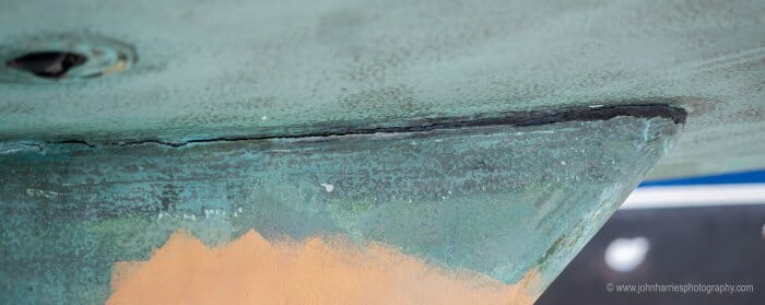
https://share.icloud.com/photos/092FpUaLj_vPhUTuk2ssIGnRg
The first time I hit a rock with this keel (freedom 28) there was a big dent in the lead and a tiny but persistent leak from the back of the keel, but no other signs of damage. The second time (don’t ask) this is what the keel looked like. The keel was bolted to a deep sump, but the movement was all at the turn where sump met bilge.
Hi James,
Yikes, that’s disturbing and a graphic demonstration of why the French A40 team are putting so much time and effort into this. Where you able to fix the boat?
Really interested in the final design. FALKEN, our new-to-us Farr 65, has a two-piece fin keel with lead bulb. The top part of the fin is a cast stainless steel hollow fairing with a flange attaching the keel to the floors and stringers inside the hull of the boat with a large array of bolts and backing plates. The lower lead bulb is in turn bolted to the bottom of this stainless fairing. So a combo lead-steel keel with all the weight low down. Seems like a complicated structure at first glance but I wonder if this kind of thing is what you mean by a lead/steel keel?
Hi Andy,
At this point we just don’t know. That said, for the A40, I would prefer to see an all lead keel since it’s just simpler and also allows us to have bronze keelbolts. I know this is possible at the 6.5 draft point because our J/109 has an all lead keel with bulb at 7′. The key is whether or not we can get the strength and impact resistance we are aiming for with all lead, but that’s, as I understand it, a reasonably straight forward engineering problem now that Maxime has quantified the forces the keel needs to withstand.
The other reason for staying away from welded keel structures is that good execution becomes more complicated. The World sailing paper I link to has some very disturbing information on exactly that, so good that it sounds like Falken’s structure does not rely on welds.
Hi Andy,
what a boat!
As you hint, this solution seems too complicated for the A40 (and not easily protective of the whole leading edge height). When we say some steel (or bronze!), it’s more likely something cast inside the lead, be it just long studs, or a more complex structure. But only further work will tell!
I’ve read Maxime’s paper and it all makes sense to me – his last comment – “There remains a fun still-to-be-investigated engineering question: is it possible to cast a lead keel with the main parts alloyed with antimony, and the absorbing part in pure lead, and have no fragility at the border between the two, and stay affordable?” begs the question, could the bumper of pure lead be bolted to the alloyed lead main body of the keel ( a vertical keel joint if you like). This would allow casting as 2 parts and removal for repairs as a possibility. There would also then be the option to have a section of shock absorbing material between the 2 lead castings all held in place with bronze bolts.
The idea of using two different alloys of lead in the keel is indeed an interesting concept. However one of the founding principles dictating the design of the A40 was that there would be no new technology that had not been proven in the field for at least a decade preferably more. I see this as a rabbit hole and a high risk expensive distraction at best.
Hi Peter,
I hear you on the dangers of innovating, but I can’t really see that this could become that big a problem to at least explore. Maxime is already contacting keel foundries to get a sense of practicality. Worst case, it’s not practical and we need to go back to the computer model with a standard lead keel and maybe reduce the target no damage speed a bit. Even then we will have advanced the cause hugely over the current state of the art, which is to build to construction standards that have proved over decades to be inadequate and don’t allow at all for impact. And we will have also confirmed with real science, instead of guesswork, that lead keels provide shock absorption.
Hi John, I have not had experience with modern boats with cast iron keels but I have sailed on and helped maintain a yacht built in 1935 with a cast iron keel. Apparently lead was in short supply because it was popular to fire the stuff at people from other countries.
The keel on this boat was still in good shape and we replaced the (steel) keel bolts easily on this yacht for piece of mind. The keel bolts were actually in really good shape and thanks to the thoughtful designer and builder were easily replaced at very low cost. The key takeaway from this experience was it mattered more that the boat was designed to be easily maintained than the materials with which it was built. Whatever the keel material and choice of fasteners for attaching it, sensible design to enable easy removal of the bolts is essential if the assembly is to be trusted long term.
Damage to the keel/hull attachment can not only be inflicted by a direct frontal hit but also in a grounding on a beach which more likely ends up with the yacht skewed sideway to the conditions. The longer the lever the greater the load. Getting the vessel off on the next high tide can result in some big loads side on, especially when another vessel is attempting to help with a tow. Every inch of extra draft is working against the stranded vessel in this case and increasing the chance of failure and further damage. The loads are sideways and not always gentle. This is advantage is even greater in areas of less tidal range, typically in the tropics where I imagine the A40 will likely be frequenting. Archimedes figured the forces in action here out some time ago. In this case the length of the lever is working against us.
I wonder if the idea of water ballast has been explored at all? Garcia use this to good effect in their high performance Cigale yachts, I also know of a high performance Bruce Farr yacht with water ballast. Not a new idea, well proven and an approach adopted by some top designers.
Water ballast seems to have many advantages
enabling a decrease in the displacement of the vessel at the flick of a switch would help with the following as a start.
Decreasing draft for given righting moment or keep the same draft with less lead, lowereing loads on hull,keel joint keelbolts etc
Lowering loads at haulout time.
Increasing chances of getting out of a stranding situation by being able to reduce displacement
Providing additional tankage if potable water was used.
Enable easy trim athwartships to give bias to leaning against a wall for maintenance in areas haulout facilities are unavailable.
Ability to trim to the lee side to keep the main full and reducing slatting, in light winds. I have seen canting keel yachts use this to their advantage. The wear and tear on sails of sailing in light winds is not to be underestimated. Shock loading of the stitching, chafe and noise often results in the motor being started to get some peace!
Tanks can form part of the structure of the vessel stiffening the hull. Breach of the hull can be isolated if it was to occur in the area of the tank. When empty the tanks could be used in a situation where buoyancy is required.
Ability to lighten ship and increase speed off the wind.
The disadvantages I see are in quick tacking in a higher wind range. In this situation it would be necessary to reef earlier.
Some reduction in storage inside the boat. These are of course water tanks so not useless.
Increase in cost and complexity of the hull, this would need to be balanced against stiffening effect of the tanks and associated baffles in a highly loaded part of the boat.
Obviously this is not going to work well for an around the cans racer, however my experience of ocean sailing has been that spending a week on one tack is not uncommon. Of course a large capacity water pump would be useful for shifting around but that’s not a bad thing to have onboard anyway.
Most likely cheaper than lead, At a pinch you can drink it and if you don’t need/want it it can go over the side. This is not a substitute for a fixed keel with an efficient shape, it is used in addition, it lowers the demands on the structure of all the ballast being at the bottom of the keel and also seem to be more versatile.
Its great to hear that the keel is most likely going to be made of lead. In my opinion it is definitely worth the increase in cost over cast iron for shock absorbency and greater density allowing improved righting moment for the given draft. From what I have seen in boatyards the modern cast iron keel is a disaster waiting to happen (or just happened). A classic example of modern business accounting ruining something for short term increased shareholder return. Probably backed up by some market research highlighting 5 top “features” which would entice someone to buy a given product. I agree, best avoided!
Hi Peter,
I agree that water ballast has many advantages. That said, I’m not sure the complication you highlight make it the right solution for the Adventure 40 where we are going for simplicity and ease of use, and also trying to keep the price reasonable at the same time. Still might be able to do something very simple by just having two water tanks, one each side, and a cross feed with a valve that could transfer at least some prior to a tack. Does mean that we would lose the best storage in the boat though.
Hi Peter and John,
in fact, the simplified pump-free (fresh)water ballast solution described by John is one I have in mind, if it turns out to be possible and to not create significant drawbacks. The “legacy” RMs (eg the RM1050) had such a setup. (Peter, by the way, Cigale is by Alubat!) In practice you keep the valve closed much of the time, with the water evenly in both tanks, and when you want the water on one side, you go heel for a few minutes.
Of course we don’t want large quantities of water ballast anyway, because ending up on the wrong tack happens!
Hi everyone,
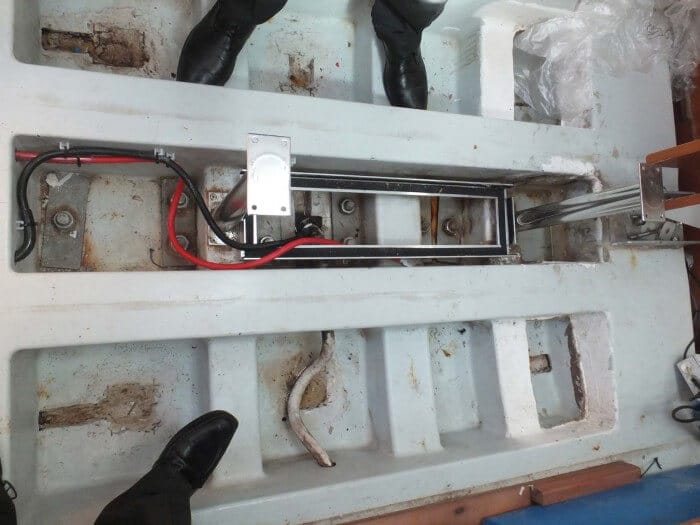
On our production Beneteau 473 we have a centre-line tank acting as our “working” freshwater supply offshore. We then have two 180 litre tanks further aft. These go underfloor from the centre line out to the turn of the bilge. We use up the water from the leeward tank offshore until empty and direct our water maker flow into the windward one until that’s full.
Heeled over 15 degrees & opening both aft tank valves (close working tank) on the distributor (see photo), much of the water drains from the windward to the leeward tank in 15 mins. Worth remembering offshore before changing tack.
One tank is like having two large guys sitting to windward (albeit not on the rail). Everything helps on long offshore legs. A direct valve / pipe connection between our two tanks would be better, but too hard to achieve after-market.
But starting with a blank canvas and if there is space, why not have 2x the normal passive fresh water tankage of a 40 foot production yacht, as active ballast?
Maxime, surely as long as the centre of gravity of the water tanks is below the centre of buoyancy, any amount of water ballast would add to, not subtract from the ultimate stability of the A40, even if it is on the wrong side temporarily? This assumes the ballast tanks are “pressed up”, reducing any free-surface effect.
Yes, you would be heeling over more than normal after an unplanned tack or when filling the leeward tanks prior to changing tack. But is that really an issue?
If all the tanks are plumbed into the freshwater system, they could provide double the normal water tankage in cruising areas where you can’t get water ashore (like many smaller Pacific Islands). And good also for those owners that fit a water maker, in anchorages where the sea water is dirty, muddy or full of microscopic sea-life ready to clog filters in five minutes run time.
Hi Rob,
I think that’s much like Maxime is thinking. That said, we have to remember that the A40 is a much smaller boat than yours and so we have to be careful not to get carried away with tankage and end up with a boat with no decent storage or payload. Another issue that will be a factor will be hull shape and if it’s possible to get any of the tankage under cabin sole, which has benefits.
As to getting caught with the lee tank full, probably not a problem, as you say, in this configuration, but we do have to think about speed of righting from a knock down too.
As usual, it’s all about trade offs, and the smaller boats get the more important it is to get the tradeoffs bang on.
Maybe this is a good use of the weight saved by the decision to build a cored epoxy hull & deck, rather than making the boat smaller than originally envisioned.
Hi Rob,
I agree that adding water tankage won’t diminish ultimate stability, provided that the tanks are not pushed too far to the side and up! My point was rather that we should think of them as a bonus, not as a reason to decrease keel weight. Regarding tank size, the specifications request 400 liters. If (at this stage it’s nothing more than an “if”) we go with the simple freshwater ballast solution, of course as you say it would make sense to go to a higher total tankage, in my mind maybe 2 times 250 liters – but as John writes, and as we’re remembered all the time when working with Vincent, we don’t have infinite space aboard a boat this size!
Hi Paul,
I wondered exactly the same thing. It will be interesting to see what the French team come up with. Maxine is talking to keel foundries as I write.
First thing I immediately thought was a front piece of the keel and two let’s say 1 inch rods that connects the front part to the rest. No idea if there is something like a press fit possible with lead. Possibly using set screws.
Perhaps an interesting perspective: The accelerative forces in Maxime’s paper, 6 and 8 g’s sustained for a total of about 50 ms, are near where whiplash could occur to an aft-facing crew member. I say this based on automobile crash test evaluations in the US that used to apply a ‘rearward extension moment’ limit of 57 N.m (assuming less than 30 ms duration as I recall) to protect against head-neck injuries. Using a head mass of 4.8 kg, and a head-neck moment arm of 15 cm, a 57 N.m moment translates to an acceleration of about 8 g’s.
Hi Steve,
Good point and good warning, as I say twice in the article and Maxime explores in his paper, a grounding at 8 knots can really hurt the crew. We are certainly not advocating for operating at that speed around the hard stuff, but I still think it makes sense to select 8 knots for modelling because so doing yields the huge safety margins we are looking for and that are non-existent on most boats built today.
Hi Steve,
that’s an interesting data point, thank you!
I should recall that the accelerations mentioned in the paper are for the points of the keel just behind the impact. I probably made things confused by comparing these to human experience. But for crew members living higher than that, the rotation component of the after-impact movement, while not changing the order of magnitude, mitigates the horizontal acceleration, removing possibly (I say possibly because it all depends on the geometrical hypotheses…) as much as half of it. Also, there is some vertical acceleration involved, depending on where the crew are…
If I run aground at 8 knots I have to accept the possibility of personal injury. At least it will be easier to attend to the injury if the boat isn’t sinking.
Hi John and all,
I reported it during the last discussion on keels, but it may bear repeating. Twenty plus years ago, 2 boats in the 40-foot range (a Beneteau and a Wauquiez if memory serves) hit a well-known, but very seductive, rock powering at cruising speed. Both came to my local boatyard for attention. One was leaking/oozing and was clearly in trouble. The other was seemingly ok till inspection found delamination both forward of the keel and aft of the keel, but that was visually ok. Both had further problems, I suspect, when examined more closely.
Both were eventually deemed total insurance write-offs as the amounts for repairs just kept mounting up in just the way you described.
I was, rather naively, appalled at their being written-off. They just looked perfect and such an easy error to make with such extreme consequences.
My best, Dick Stevenson, s/v Alchemy
Hi Dick,
You are right, a disturbing number of boats are written off due to keel problems. There is a 10 year old Beneteau Oceanis 50 at our local boat yard with a keel that moves 10″ either way when being pushed as she hangs in the slings and the grid totally disconnected from the hull. I checked carefully and there is no sign of grounding and yet it’s difficult to see how this boat could be fixed properly at a cost that would make it worth saving her.
So grounding appears to be very expensive in non-A40 designs. Presumably insurers pay. Can A40 owners expect to have smaller insurance costs?
Hi PD,
I guess that’s a possibility, after all insurers give discounts when boat monitoring systems are installed.
Hi John
Another way of dissipating the energy of a grounding is to have a very old fashioned underwater profile sweeping from the forefoot to the aft end of the keel. I can say from hard experience that the boat will toboggan up on an obstruction, becoming thoroughly stuck as the lead keel conforms to the rough rock surface, but most of the damage will be to the skipper’s dignity. I realize that this sort of keel profile is not very efficient going to windward and not appropriate for the A40, but it does resolve the structural damage problem.
Also, damage from an abrupt halt is not limited to the boat. A few years ago in Scotland, a fin keel boat that we were were close to came to a very sudden stop against a rock at full speed. The skipper had significant injuries from a face plant into the binnacle and one of the crew had to be airlifted to Glasgow as a result of pitching down the main companionway.
Wilson
On my old Aussie steelie the cutaway forefoot has just that shape you describe – plus there is a 60mm solid round bar running from the waterline down to the 19mm steel plate that is the base of the keel, that forms the leading edge.
John of course will hate it for sailing performance, but I will be sitting out this thread with a fine sense of smug all the same.
Hit a rock at 8 1/2 knots with 45ft 20t steel with cutout forefoot.
A substantial dent in encapsulated keel which was simply faired over. Interestingly the water tank that was built in at the forward part of the keel had the internal welding ripped apart as the steel flexed which resulted in the bilge water entering the fresh water tank. No one was injured despite being thrown forward.
The yacht rode up and onto the rock which would have reduced the severity of the impact.
On the new build with 58t moving at 10 knots and with 3.2m draft we did the engineering paying particular attention to the downward force at the forward edge of the keel and the upward force at the aft edge and reinforcing accordingly.
Another point of difference is the the top sides of the keel protrude 180mm into the bilge rather than simply join to the hull creating a stiffer structure and allowing for a weld both internally and externally. Finite element modelling is very useful here.
Finally while looking at keel attachment and hull support we should also consider the hull support in regard to rudder stock loads.
Having modelled the distortion of a soft lead keel it should be a simple exercise to model a lead/antimony keel which I believe will show a sufficient degree of obsorption.
Hi Steve, Alastair, Mal, Stein, Reed, James, Dick, Wilson, William,
many thanks for the real-word stories you’re bringing!! They’re really helpful in solidifying and refining the thinking on this issue.
What do you think about the Keel-Pro? A water-filled rubber bomber on the keel.
A hollow rubber nose mounted on the keel, serving as a bumper. It is made in Sweden by the Swedish company Svenska Koster, see web page http://www.svenskakoster.se/page6/index.html.
There is a link to the page “Keel-Pro Info In English”. On the Swedish pages there are some photos that will be comprehensible also for English-speakers. I have never seen the Keel-Pro and have no experience of it. Could it be of interest?
Hi Carl,
That’s very interesting. I’m betting that Maxime will at least want to talk to them.
Hi Carl,
thank you for pointing out the “Keel-Pro”! Very interesting indeed, and always good to know that we are not alone trying to solve this issue.
And John, well guessed, I just sent them an email!
Thanks for that link, Carl. The “Keel-Pro” is, I think, an excellent idea. Using the seawater inside the resilient rubber cavity as the damping fluid for a shock absorber is really rather brilliant.
As a retrofit to an existing boat, it could be a bit costly in labour. But what if that technology were designed into a new boat from the start, with the mating profile to accept it already cast into the keel’s leading edge right from the foundry? Then you are looking at just a few minutes to install it, plus the cost of the cast synthetic rubber itself, which I expect would be relatively affordable in quantity.
H Matt,
Good to hear that it makes sense to you, at least on initial view.
Hi Carl,
The Keel-Pro looks like an interesting product. Rubber in the correct durometer can definitely be a decent energy absorber (and will return a lot of the energy rather than something that is plastically deforming but this shouldn’t be a big issue). The idea to make it a fluid damper is interesting. Fluid dampers can work great and have great power density. The trick is that these usually operate at quite high pressures and it would be interesting to see how to design one out of rubber with such a big chamber and loose tolerances.
To me the question here is one of details. Stuff like this has to be tuned appropriately and can be dependent on things like temperature. If you want a highly effective system, then it needs to be tailored to the different boats, maybe you could do it based solely on displacement and something like depth of keel below COM or even just depth, Maxime would know better. Then I have the question of how it performs over time. Rubber is notorious for degrading if not heavily filled so it needs to be the right material and then its lifetime needs to be understood. Also, if you are using orifices, then these need to be kept clear unless the pressures are so high it will automatically clear. Finally, any bonding process needs to be proved over time, bonding is not easy to make work over long periods of times with thermal cycles, immersion, etc. With enough time and budget, these obstacles could likely be overcome but a seat of the pants pretengineering approach probably wouldn’t add anything useful.
Eric
Hi Eric,
That, together with your other comment on lead, give me the feeling that while the rubber bumper might work when all was within tolerance, lead might be a more forgiving solution in the real world, particularly as the boat ages. Maxime has also had some great news on the practicality of casting a keel with both alloyed and non-alloyed lead, but I will let him share that when he feels it’s time.
Hi John,
in fact, the great news so far is that it’s now pretty sure I will be able to gather all the necessary information and expertise we need on lead – but there’s still much work before we fully understand what specific route to take!
Hi John,
I completely agree that the goal is to spread out the loading over time. It is a fixed amount of energy so you can only impact how long it is dissipated over and what the shape of the curve looks like. Out of curiosity, do you if an analysis was done to relate the vertical point of impact and the peak loads seen? I would guess that most of the time the hits are near the bottom of the keel but certainly there must be times that they are significantly far up and that makes for a different problem as the boat will pitch less so this is working against the improved moment arm relative to the keel joint.
In engineering analysis, it is far easier to run a basic linear static analysis than do a proper dynamic non-linear analysis. I would estimate that <10% of practicing mechanical engineers are actually qualified to do a proper impact analysis that gives them an answer within 20% of the real value. Anyone can get a program like Ansys to spit out pretty pictures but having those pictures mean something is a totally different ballgame. In the team that I lead, we actually have people whose job consists almost entirely of running various dynamic and non-linear analyses, to be good at it, you really need to specialize. To get around this, people who are not specialists often try to convert impact loads to an equivalent static force they can plug into their analysis. In some applications this works really well but on average it is a pretty poor approximation. When you convert to a static load, that incentivizes you to make a structure as strong as possible independent of the stiffness. Then when there actually is a dynamic load, you may well find that your stronger structure is actually the first to fail as the loads are even higher. The classic example is people reaching for carbon fiber in an impact application because they are not adjusting their static model for the stiffness of the material. Given that this analysis was done by a university, the professors should be able to guide the students properly even if the students are not up to it on their own. Since there is no information in the report on stuff like mesh, boundary conditions, number of steps, etc it is impossible to evaluate from afar.
I believe that most sailboat keels are 3% antimony or so. My materials handbook doesn’t have this exact value but given the values on either side, I would think that would mean that pure lead would have a tensile strength around 1/2 of the 3% antimony alloy (18 MPa vs 32 MPa). Unfortunately I don’t have a comparison of elongation at break, modulus and a few other characteristics which would be useful to know. While the strength difference is significant, it also is small enough to suggest that if this proves to be very hard, the situation isn’t hopeless and a few other design changes may get to a good result as well.
Thank you for linking that report by World Sailing, I had not seen that. The actual engineering discussion is a breath of fresh air in comparison to most times I read the word fatigue written in articles about sailing, the author knows what they are talking about and doesn’t treat fatigue as an unquantifiable demon that could spring at any time. Since the point of this article is grounding resistance, I am not entirely sure how the report is applicable other than if the structure is already significantly compromised but that would represent very poor design for a cruising boat in my opinion (okay, there will be a very small degradation but we shouldn’t be operating at a point in the S-N curve that represents a number of cycles similar to real ones). I definitely hope that the A40 does not get involved in a welded keel structure. Of the keel failures I am aware of, a very significant portion are welded structures and they are failing for the reasons in the World Sailing report and basic corrosion. Designing for welding requires specialized knowledge and then there needs to be a lot of process control on the actual welding and inspection which is all doable but far too much effort to me for a structure that is actually not stressed very much, the stress is at the joint and even that is not horrendous.
I am curious to hear the answer on whether this can actually be cast as proposed. I have done a lot of castings over the years but never tried to combine materials, when we need different properties we have always done it through post processing or geometry.
Of course, if the bumper idea doesn’t work, you could do it with geometry but that would be harder to repair. The automotive and aircraft industries have really made a science out of developing geometries that fail repeatably and are tuned to dissipate energy in the desired way. On a keel I would think this would look something like a lead casting with some material near the front removed based on FEA results and then replaced with non-structural filler. I see a few drawbacks of doing this, the biggest one being whether the average person/yard could repair to original. Also, there might be nuisance cracking which would definitely catch a surveyors eye and many would probably point to a previous major accident as the reason they found filler rather than the exact opposite.
Eric
Hi Eric,
many thanks for your input!! And great to read that you agree on how to define the issue, and especially on the danger of just thinking “well, let’s make everything beefier!”.
As to relating the peak loads and the height of the point of impact, yes, that’s the “short calculation” mentioned in the first page of the paper! The hack is to denote the momentum transfered from the boat to planet Earth, write down the equation of momentum conservation, then the same for angular momentum, then cancel out the above-mentionned momentum between the two equations, and you get that the initial energy is divided between the structure and leftover rotation movement in a ratio governed by the squares of two distances, namely the vertical distance between the center of mass and the impact, and d where I=md². When you take likely values for these two distances, you find that, even if the shock happens at the bottom of the keel, it’s unlikely that the rotation movement will carry much more than one third of the initial energy. So basically the problem is not changed much by the height of the impact.
(on that basis, we computed the “apparent” mass of the boat to be 75% of her “real” mass, as a more or less careful representation of the most likely impact, the one at the bottom of the keel)
Regarding the computation, mesh and timestep sizes etc. were checked by others, but in fact we didn’t go through all the checks that would make absolutely sure that the results hold. For instance in the 8-knot simulation, we didn’t go check if in some corner the strains go beyond the validity range of the equation, with rupture happenning. But I think we don’t need to, at this step: the goal was just to get a sense of the general behaviour, and learn that taking the lead thing one step further than usual will very likely be relevant. (although one could argue that this was almost visible “by hand”, with a back-of-enveloppe calculation starting with the stress-strain curve of lead…)
And yes, it seems that most lead keels are close to 3% antimony – although I should learn more in the coming weeks. So I do agree, if it appears that using pure lead is not practical, it will still be possible to do things with the geometry!
Hi Maxime,
Sorry, I had missed the discussion of the height of impact, thanks for explaining that again.
Thanks for sending that site. My high school French classes failed me here but the graphs were useful. One important thing that they show to me is that there is not an abrupt break with any of the alloys shown, getting an accurate 2% offset yield number for pure lead must be a bit tricky. This makes it pretty ideal as an energy absorbing material assuming it is not an application that takes repeated hits but that shouldn’t be a keel. I assume the hydrodynamic forces are quite low and that the strength of pure lead is not an issue. Out of curiosity I did a quick calculation of what a typical 40′ boat might look like if it was picked up by a hydraulic trailer on a single steel beam as is not uncommon (10,000kg/100mm*100mm= 10MPa) and small localized flattening/indenting could well be possible if the pure lead went down into the area being picked up and the bulb had little or not flat bottom or the boat and beam are not well aligned. I wouldn’t expect there to be any issues beyond a few small marks but it is interesting to have such a weak material in play.
Eric
Hi Eric and Maxime,
A fascinating discussion between you two, although I have to admit a good deal of it is way past my pay grade, so clearly the right thing for me to do is keep quiet other than to say it’s good to hear that both Eric and Matt think that this approach is the right one.
Hi Again Eric,
I agree that the WS report does not directly apply given that it’s mostly about welded steel structures, but, as I write in the foot note, I mentioned and linked to it to show that the current ISO construction regulations, regardless of how the keel is built, have far too little safety margin and make no attempt to produce keels that can withstand even modest groundings.
And the Wolfson unit investigation independently came to the same conclusion for a keel that did not depend on welds.
To me this is the biggest problem facing offshore sailing today, so anything I can do here at AAC, no matter how modest, to make the problem more widely known is a good thing.
The good news is that World Sailing seems to agree so hopefully we will see an improvement to the standards, although when that will be, who knows.
Hi John,
Yes, from the standpoint of showing that the existing standards are inadequate, it does a very good job. And if one area of a standard is lacking, it definitely calls into question the rest of it. My comment was simply that the S-N curves and analysis methods mentioned hopefully don’t apply to designing for a grounding. I do appreciate you calling attention to this.
Eric
I used truck dock rubbers as stops on the quadrant.
These are simply glued to steel backing plates with special glues. It should be possible to glue the same rubber to steel which is then screwed to the lead. These allow for 60t impacts albeit at low speed. I believe that water filled bumpers would disintegrate on impact before absorbing much load.
Hi William,
I wondered how much force a water filled bumper would absorb too. That said, it did seem that they had tested the idea so it will be very interesting to see what Maxime thinks of the idea once he has investigated further.
This feels very good. Congratulations to Maxime and team.
I owned an X Yachts X332. They claimed the keel could withstand a grounding at full speed (I didn’t test the claim!). X332s and most X yachts designs have a galvanised frame inside that the keel was bolted to. This is featured in the advertising. Latest designs have carbon fibre rather than galvanised frames. I’m sure Maxime will be familiar with X Yachts design, but just in case…. An added advantage on the X332 was a position on the frame that you could shackle a lifting strop. This was taken up through a dedicated opening that required the companion way hatch to be in the closed position. This made it possible to use any crane to lift the boat safely. Feature was there for this and to allow easy weighing for racing.
Hi David,
I agree the X Yacht way is very good. Nautor Swan used to do the same and I was looking at one today in the yard that must be 40 years old, has clearly been run aground a couple of times, and yet to keel to hull joint still looks near perfect. It can be done.
John
Suggest considering 954 Nickle Bronze Aluminum Alloy.
for keel bolts. Increased yield, same labor cost.
Pedr Turner
SV Maizuru
Hi Pedr,
Sounds good, although I’m not qualified to comment, or even have anything to do with the final alloy selection for the keel bolts. That said, I’m sure Maxime will be able to get good advice on that in France. In my experience generally poor materials don’t end up on boats due to ignorance about these things, but rather because of cost cutting or sourcing ease. We will need to guard against that every step of the way and having members with specific expertise will be a huge help.
Here are links to a story about a very high-end wood composite yacht that ran into a rock immediately after completing a major refit at an expensive boatyard, causing major damage to the centreline structure.
There are very good pictures of the original bronze grid fabrication and the new carbon fibre grid that replaces it. The new design includes what they refer to as “fuse” bolts at the leading edge of the keel and a crush zone at the trailing edge to absorb the energy of the next grounding without wrecking the centreline structure again.
https://stephenswaring.com/zemphira-returns-to-the-shed/
https://stephenswaring.com/zemphira-update/
https://stephenswaring.com/zemphira2022/
It would be way beyond me to have a substantive opinion about this repair, but the designers, Stephens Waring, have a top notch reputation in spare-no-expense land. As an example it’s probably not particularly relevant to the A-40 but is interesting for we boat nerds.
Hi Wilson,
A very interesting read indeed. Like you, the engineering is way mast my pay grade, but the big take away for me is this confirms once again that no matter how strong a keel to hull joint is built, and even if you have limitless money to spend, there must be a failure point somewhere to absorb the forces in a really bad grounding.
One thing I did wonder about was how they have engineered the zone between very stiff carbon and quite flexible wood. Matt wrote a post over at his site some years ago about the difficulties that arise when we mix materials of different stiffness in a single structure.
“Cruisers are divided into two groups, those who have run aground, and those who lie about it.”
I wonder if there is any relationship between draft and the frequency of grounding. Maybe deep draft sailors don’t take the risks that shoal draft sailors might be tempted to take. On the other hand, maybe they take more risk*
Any marine actuaries in this group?
* https://www.morganscloud.com/2022/05/23/adventure-40-keel-draft-and-shape/#comment-302873
Hi PD,
I had a friend who sailed the Bahamas in a deeper draft boat (2m, 6.5 ft) and was careful, and never/rarely went aground. When he started sailing the Bahamas exclusively, with glee, he finally got a shoat draft boat and started pushing the limits and went aground with some regularity when exploring regions closed off to him before.
His attitude became, and I agree, that going aground is no big deal if done at poking-around speeds in settled weather with a dinghy in the water (if even necessary) to kedge off. Too many really nice cruising grounds are considered “off limits” if you are unwilling to go aground.
I do not believe it is still the case, but the charts in Belize used to be merely suggestions of what you might find and bumping one’s way into a nice nook, while not common, certainly happened.
My best, Dick Stevenson, s/v Alchemy
Any updates on the structural attachment between the keel and hull to manage the 8 knot grounding goal?
From the recent renders it still appears to be a very thin keel attaching directly into the bottom of the hull with no keel stub or other mechanism to distribute the impact force.
Hi Charlie,
Maxime has done a lot of work on this with keel builders and engineers and has written another paper, which we will be sharing soon.
This is all about some pretty complex engineering so a look at a rendering does not tell us anything useful. For example said rendering would not show the mechanisms for distribute and ameliorate keel impacts that could, depending on final engineering, include all kinds of keel to hull joint reinforcing that would be invisible from outside the boat and in a rendering.
That said, there is a clue to Maximes’ hard work on one of the renderings, if we look hard enough.
I don’t have any doubts about the strength and fitness of the final approach. I have confidence that Maxime has put in a lot of work and will come up with a good solution. Also agree that a rendering is not a good source of data for engineering analysis 🙂
I’m just excited about the progress of the A40 and eager to learn more. Glad to hear that you’ve got plans sharing the new paper soon. Thanks!
When refreshing the A40 book over winter it’d be awesome if you found time to expand “ground” to include other below-surface hazards like floating containers and rudder-fixated orcas, and added the hull and rudder to the keel when describing the A40’s collision-mitigating features. Perhaps the hull won’t be cored fwd below the wl and/or the fwd cabin door might be watertight.
Hi PD,
I don’t think it’s practical to build a boat that can withstand a full speed collision with a container or for that matter a rudder that will withstand the efforts of a really determined Orca. On the latter, we will be thinking about and making provision for rudder damage.
It’s also not possible to make the forward cabin door watertight without a huge hit on the usability. And it’s doubtful that a water tight forward cabin would make a lot of difference.
That said, the forepeak bulkhead will be watertight and Maxime is looking at making the bulkhead forward of the rudder post watertight, although that might be too big a hit to storage.
We can certainly look at the puncture resistance of the hull but we also need to balance that against weight forward, the worst possible place for it.
More on watertight bulkhead tradeoffs and container risk: https://www.morganscloud.com/2013/08/19/risk-management-and-watertight-bulkheads/