
Wouldn’t you know it, as soon as we put our McCurdy and Rhodes cutter on the market last summer, the Simrad/Robertson autopilot brain that had been reliable for over 20 years and at least 100,000 miles decided to turn its little electronic toes to the air.
And, of course, the new B&G brain I selected—mainly because it is a successor to the old one and therefore compatible with the existing bomb-proof drive comprising a Simrad hydraulic pump and massive ram—is all NMEA 2000, while the old brain was a combination of proprietary connections (Simrad Robnet) and NMEA 0183.
The new brain also came with a new digital compass and needed to be controlled by the B&G Plotter we installed a couple of years back in anticipation of just this scenario, all NMEA 2000.
Easy Peasy
Still, after getting the new kit installed and working, I was confident that getting the networks integrated would be easy and take half an hour or so. After all, I’m an electronics technician by trade and I have been messing with boat networks for 35 years. How hard could this be?
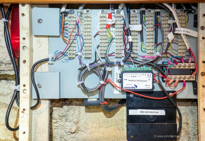
Particularly since we have always kept our NMEA 0183 network well organized with multi-conductor cables from each unit routed into a central patch panel (see photo at top of article) that Phyllis built, documented and labeled—she turns being organized into an art form.

And, further, when we added the plotter I documented the simple NMEA 2000 network in Maretron’s excellent N2K Builder.
Not So Easy
How wrong I was. A few hours into the project about half the electronics on the boat were having a sulk and not talking to the other half, and I was becoming increasingly confused and frustrated as I changed wiring and software settings only to fix one thing but break another.
Time for a deep breath and a rethink.
After staring into space for a while—really hope my mouth was not hanging open as at my age this is a look to avoid at all costs—I realized that the answer to this was to stop changing wiring and settings and instead plan and document the new network first.
A Better Way
And that’s what this article is about, an easy way to:
- Plan and document
- Install
- Modify documentation to reflect as built
- Iterate steps 2 and 3 until everything works
At first glance the answer would seem to be to draw the whole thing out in the form of a circuit diagram, but actually that’s a laborious and error-prone way to go about any wiring documentation, not just networks.
What, you say? Everyone knows a schematic is the way it’s done. And yes, that would have been true…up until about 1970. But there’s a better way.
Let me explain. Back then I was a mainframe computer technician charged with keeping several new generation room-sized computers functioning—yup, you calculated right, I was 19, it’s a long story.
These computers were among the first to have no drawn schematics, primarily because the stack of drawings would have been 20-feet high and impossible to maintain as modifications and improvements were made.
Instead, the entire computer was documented in a few big books of Boolean algebra equations, liberally annotated, with pinouts. Brilliant, and way easier to troubleshoot.
Don’t worry, I’m not going to try and teach you Boolean algebra, particularly since I have long forgotten most of mine, but the concept of documenting with written lists, rather than drawings, is the same, and by far the best way to document all the wiring on our boats, not just networks.
To do this we need two documents:
- A data flow list that shows where each piece of information originates and what devices it goes to.
- A pinout list that tells us where each wire starts and ends and the position on a junction block or plug as well as what colour it is, so we can quickly go right to it, either to make a change or troubleshoot.
I guess you could try to combine the two, but I find that’s both more confusing and time consuming.
By far the best tool I have found to produce both is a spreadsheet, even though I’m really just using it as a table layout app, and not doing any calculation. I use Excel, but Google Sheets or Apple Numbers will do just fine.
At this point I could blather on for thousands of words telling you how to do this, but let’s not. Boring, boring, dull.
Instead, let’s look at how I quickly resolved my network nightmare above and, without any added effort, ended up with documentation that will make the new owner’s life way easier for years to come:
I try to document also anything I install on the boat, as when I want to modify things, it is much better to check my own connection document rather than search in manuals.
I also write down a wires that are on device but not yet connected to anything (loose wires), as there might be time I will need to use them later, and again, easier to look on your own docs for this.
Hi Taras,
I can see that, although now days with easily searchable PDF manuals, I prefer to mark up the actual manual with what I did. PDF expert also has bookmarks, so super fast o find what I’m looking for.
Sorry John, glazing over here. But that’s ok, I’ve had 6 decades to come to terms with having a lame-brain. What I have learned is to justify my mental laziness. In this case: “I don’t want to integrate my electrickery because (a) it means I am more hands on with the navigation, and (b) it means if (when) something goes down it doesn’t take anything else with it.” Of course there’s the other significant factor: time spent on marine electronics is time away from varnishing my teak. So the question is: Do we actually need to have all our gadgets talking to each other? What are the advantages and disadvantages? I’m sure these questions are answered in your further reading, but maybe a quick 25 words or less that doesn’t have me rushing for my turps and varnish.
Love your work,
Mark
Hi Mark,
That’s a perfectly sensible approach. The key to all of this is going with our strengths. You will be way safer (and have more fun) than if you distort yourself.
And further, I won’t hold the varnishing thing against you since one of the best friends has the same affliction. 🙂
He is also one of the best seaman I know and has almost no electrickery and nothing networked on his boat.
Hi John,
Mark explains not getting this with a joke about having a lame brain. I’m the same age, but still believe that I’m kinda smart. On the other hand, I’m smart enough to know that’s an illusion. 🙂 Anyway, same result: I struggle with understanding the method, its components and how to deploy it. I do understand and agree that a descriptive list can be better than a drawing, but I’m still feeling a bit like I missed the essential first lesson of a course, where the fundamentals were explained.
When explaining things i know very well, I often forget to include information that I intuitively expect everybody to know. Like when teaching sailing to total newbies. When the wind is very noticeable, I just can’t understand how it’s possible to not know which direction it comes from. Still that’s normal. Thus, when I start talking about the sails and their angles and shapes, they draw a blank. What I say makes zero sense to them. In this article, I felt like that type of newbie where i needed a key understanding before I could grasp the content.
So, should I use this opportunity to grasp that i actually do have a lame/lazy brain, or could you supply some more basics about the use of the lists?
Hi Stein,
Great to hear from you, I was starting to wonder where you were!
Good point on the basics. I started off that way, but then realized it was going to go 5000 words and that the basic point (use lists not drawings and the importance of data flow) would get lost. It’s a hard one.
Did you check out the links in further reading? A lot of the reasoning is covered there and I did not want to duplicate all that.
All that said, if there’s enough interest I could break some of this out, like the Actisense stuff, in separate post referencing this one.
Hi John,
I’m still paying attention and reading everything here. That’s not gonna stop until I have a significant amount of earth above me. 🙂 The reason I’ve written less is probably partially accidental, that I haven’t felt I could contribute with value. Also it’s because I’m away from home 5 days a week for hard work and then the remaining days I work with projects on our own boat. We have some ambitions about getting several bigger jobs finished before 15th of June, when we go to Norway, if the rules get a bit relaxed. So my spare time and energy for anything else than sleep is limited. Anyway, we’re getting stuff done and looking a lot forward to sailing!
I didn’t check out the links, so I’ll do that. I’ll get back with a comment if there are things i don’t get. Maybe I find that my brain can still understand new things? 😀
Hi Stein,
Ah the work thing, such a pain in the neck when we want to go sailing!
And finaly, it being the 17th of May, Gratulerer med dagen
Hi John,
I have found what works best for me is an Excel document listing each wire from source to destination with all the steps along the way and listing color, location, polarity function, etc. as well as a CAD drawing like the attached. I think a data flow document is a great idea for the NMEA nav data and I plan to create one of those as well.
Philip
Hi Philip,
That’s exactly what I do for DC wiring, except you are way better and neater than I am, and I use excel. Going to do another short post on exactly that. May I use your diagram to illustrate?
Yes, please use the diagram. I used BricsCAD, which uses most of the same commands as AutoCAD but is a lot cheaper.
John,
I agree with your approach, and you have helped me realise how to do the documentation better. I wish previous owners had acted on it!
However, given the article’s title, I feel there is another matter and warning that should be closely linked to this. That is the huge danger of data backbones, particularly when implemented in such a way (as per NMEA2000) that a single piece of damage or loose termination takes the whole thing (with everything on it) down.
I managed to rewire my boat whilst completely avoiding NMEA2000, prompted by your earlier advice. The NMEA2000 backbone is simple to do (if expensive) but a massive single point of failure, so unacceptable.
I admit that this did not include the autopilot, and I fear that I will be forced to use NMEA2000 for that link when I do it, because there seems to be no other option. But it will only handle that link, so can be isolated.
But everything else will remain based on point-to-point NMEA, with a hub/bridge/bi-direction converter (in my case Digital Yacht: they have a wide range of options and are very easy to configure, including Raymarine Seatalk conversion both ways: way more flexible and cheaper than Actisense etc). This also gives me an output of everything to computer (wired) or to WiFi, such that display devices can interact with it when needed.
Is there reason to move on in our thinking on reliability of data buses? If not, should there not be a big risk warning attached to this article….
Best wishes, Richard
Hi Richard,
Very good point, and I link to the warning in Further Reading, and also kind of cover it in my sentence:
Great idea for keeping track of my ongoing electrical refit; and in general documenting what’s connected to what, and how. Electrical, data, and plumbing.
What I use on Windows for planning and documenting the boat electrical refit work and general construction:
LibreOffice Draw for making high level layout and connection drawings, and LibreOffice Calc for spreadsheets. Okular is not bad as a PDF viewer and annotator. For all things text and programming related, I use Kate. To tie it all together, I use the Freeplane mind map tool (as prompted by another article on this site). My years of Linux use steered me to most of my choices. The tools are free, and quite stable and feature rich by now. And some are even now in the Microsoft Store (for better or worse).
For Draw: Using line colors, etc. and line connectors makes electrical layout easy, and the picture often prompts for what I have forgotten. For general fabrication and documentation of simple shapes, the ability to do floating dimension lines (or just snap the dimension shape in), makes that effort pretty painless.
Not as powerful as AutoCAD or TurboCAD, but much faster for me. And I even cobble up an orthogonal view by hand when needed, from the plan, etc. views. For sending to someone else, the print to PDF has been adequate so far.
Of course, MS Office and Visio are more polished, and allow collaboration, as do the CAD tools. I just don’t have the need right now. Outside of a TurboCAD drawing of my boat, inside and outside – slow going on that effort. But I sure wish I had one.
For Calc: I always add a sequential numbering scheme to the first column, so when I sort, I can get back to the original view. That works well for me when using a spreadsheet as a structured note taking tool. In my case, say, sort by fuse size and type, to help generate a BOM, then restore the original view.
Somewhat unrelated, but my years of data center work taught me the value of adding the same unique serial number to each end of every cable that goes into a bundle, or through a bulkhead, etc. I just print up 2 copies of a sequence of 3 digit numbers (6 digits for the thousands of cables in a data center) on the label printer, that wraps around the cable.
Printed sideways repeating on the label, so you can see the number without twisting the cable. You just have to keep track of where you left off in the sequence. Then I also add a flag type or wrap around descriptive label if I want. No more tracing wires to verify. And it shows me what I have replaced, or traced out.
Hi Glenn,
All sounds good to me, and very organized, albeit it may be a bit geeky for many readers without your tech background.
Re. labelling both ends of every wire – Absolutely. This makes life *so* much easier in the long run. After a few bad experiences with label printers and tape, I have a preference for the embossed plastic clip-on wire number tags, particularly if they’re colour-coded. They’re sure to still be readable in 30 years.
And it’s important to keep in mind that, for this entire exercise to be useful, you need to do it consistently and uniformly, and update the documentation right away, and make sure old documentation is no longer in circulation. (A git repository is great for that.) Systems where the hastily patched-in modifications no longer match the out-of-date pinout list are a real whack of fun.
Hi Matt,
I agree that updating is vital. This is a lot of why I have, after experimenting with drawings in CAD, gone to simple lists in excel. Just so much easier to update when a change is made. In CAD I was always discouraged from updating “oh shit, I have not used cad in a year and now I have to relearn it just to make one simple change”. This is one of those cases where done is better than pretty.
Of course for those that use CAD every day as part of their work, that does not apply.
Thanks John,
One of the things I love about this site is that it has significantly reduced the number of unknown unknowns in my sailing knowledge. Add to the list pinout. I know what a pinup is….. but even with:
A data flow list that shows where each piece of information originates and what devices it goes to.
A pinout list that tells us where each wire starts and ends and the position on a junction block or plug as well as what colour it is, so we can quickly go right to it, either to make a change or troubleshoot.
I still don’t see the difference. Can you elaborate on what the difference between them is about?
Hi Michael,
Perhaps an example will help.
A pin out list might tell you that a red wire is connected to pin 2 on the AIS transponder and to pin 3 on the SeaLevel box, but that’s all it tells you. Not a lot of help if you are trying to figure out why the computer is not displaying AIS targets or has lost position, or maybe heading, data.
A data flow diagram tells you that said wire, and several others, carries NMEA 0183 and that you need to the AIS configured to send AIS targets, gps position and heading as well as course over ground.
And further that the AIS spec requires a BAUD rate of 38400, so clearly all devices in chain must understand that baud rate (most don’t). And that the sea level box converts that signal to USB and then passes it to the navigation computer as the primary of two position inputs.
And further, a glance tells you that if that feed loses position a quick change in software configuration on the computer will get you back up and running using the position that comes from the B&G plotter via NMEA 2000 through the Actisence converter to USB.
But wait, you say, where the heck is heading coming from (requires a compass) for crying out loud. Once again a quick glance at data flow shows you that came from the B&G heading sensor, as a NMEA 2000 output, and then was converted by an Actisense box to 0183 and passed to the AIS which multiplexes (mix and pass through) it with it’s own data (AIS and Position).
With a data flow diagram we can easily trouble shoot missing data because we know where it should be coming from and what devices are in the chain.
Thanks, that makes sense.
A great discussion on the art of network management. I find that difficult to say when I am thinking about a sail boat. But it is the 21st century and A person needs to know where they are and enable the boat to guide itself while playing with the sails.
As far as the PDF file programs, while working they were an essential tool to communicate ideas and maintain a format while sending them between computers. I had a love hate relationship with Adobe. I worked around the control Adobe exercised by using a fax software to add signature images, then printing the image in a PDF format. Clunky but effective. Then I discovered “CutePDF” by ACRO Software. https://www.cutepdf.com/products/
Not sure how they accomplished it but at $50 it was a great application for the PC.
Now to just go back to the boat and document my networked systems. Fortunately it is a minimalists approach so should take me less than a day… I hope.
Where or who to start troubleshooting with?
I lost my wind instruments on the way up the Chesapeake last month in 30 to 40 gusts. I figured masthead was gone. Then Depth fagged out and then GPS. In Charleston I had a new motor put in the SimRad Autohelm. At the time they updated the Chartplotter at the helm. It has since had an error message that it failed to update. I have a Zeus 10 under dodger and a newer one at the helm. I have 4 BG modules over the companionway. All worked fine with exception of error message until a week or so later with the wind. I bought a new windvane, replaced and things worked for a few hours and then Depth and then wind went dark. Unplugging the wind from the network and placing in a plug makes the GPS more consistent-but it does cut out.
Would the best guess be to just update the Software again? It had been flawless for the past 3 years.
Rob
Hi Rob,
It’s really hard to trouble shoot these kinds of things at a distance, but the first thing I would do would be to get everything updated to the latest software. Once you update one item on a network it’s really important to update all others.
You also want to get rid of those error messages since they may indicate that the update is partially done.
One thought for you, does the NMEA 2000 go all the way to the top of the mast? If so, that might be causing you network issues and things changed when you replaced the masthead sender. If so, best practice is to go with a mast sender that uses NMEA 0183 to the base of the mast and then converts to NMEA 2000. That’s how the newer wired sensors from B&G work.
My guess is somewhere in all of this the NMEA 2000 network had a problem introduced. Might just be a plug not seated properly.