
In the last chapter I explained Ohm’s Law, that wonderfully elegant and simple relationship between three variables that allows us to clearly understand just about any problem we have with our boat’s electrical system.
Now let’s look at some practical applications: how batteries charge and voltage regulators work—two of the most misunderstood pieces of gear on a voyaging boat.
To make this easy, we are going to use lead-acid batteries in all or our examples. Yes, I know, you want lithium. That’s fine, we will get to those in a later chapter and the stuff we learn in this chapter will make understanding lithium systems way easier.
First we need to do one of those algebra trickery things (that we all slept through in school) so Ohm’s Law will get us the answer for any one variable as long as we know two others: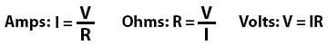 That is:
- Amps equal volts divided by ohms.
- Ohms equal volts divided by amps.
- Volts equal amps multiplied by ohms.
Real World
Now let’s say:
- Our system is 12 volt.
- Our lead-acid battery bank has 400 amp hours capacity and is half discharged.
- We are sailing along using 20 amps for various loads.
- We have 200 watts of solar panels and it’s sunny so they are putting out 100% of their capacity—unlikely, but it doesn’t matter for our purposes.
- We have a 100 amp alternator on the engine.
- Both the solar panels and the alternator have regulators.
Well done, John. I think this is going into the log book to edify the rest of the crew.
Hi John
Good article.
There is one thing that I do not understand. Where du you get the 120A from in point four under “Get charged”? Or ist this rounded up from 116.66A?
Hi Enno,
Woops! I rounded up, but should not have as it makes things confusing. I will fix it. Thanks very much for the correction.
Hi John
A small point. Watt hours or kilowatt hours are a measure of the amount of work done or energy expended. Power is measure of work done in a period of time or Work divided by Time. So multipying it by Time , the two “Times”cancel out and you are left with Work.
Hi Bryant,
You are, of course right…although I have to admit that I had to look it up. However, given our goal here to only burden people with what they need to know to manage their electrical system I think I will leave it as it is, rather than introduce another term.
Hi John
I was just trying to help your Science teacher to stop revolving by pointing out a small thing that in no way detracts from a really useful Article . You are right that demystifying seemingly unnecessarily complicated electrical systems by the application of some simple science basics will benefit us all.
Thanks for the valuable article
Hi Bryant,
No worries, I just didn’t want the discussion to veer off into the more esoteric aspects…particularly since I might get out of my depth!
I would vote to fix it because it is at the root of some other misconceptions. In the true engineering sense, kW-hr is a ridiculous term, similar to saying I filled up my boat with 20 gals/hr-hrs at the fuel pump. It’s just gallons. For energy, it’s just joules (or kJ or MJ). A joule is a Watt-second so that is the right term, but I acknowledge that multiplying/dividing by 3600 is hard and kW-hrs are here to stay so…
But the other confusions driven by this lack of understanding are things like “I need 100 kW-hrs but I only have a 50 kW engine so I have to get a bigger engine” and other foolishness. Right up there with people saying they have a “500 amp battery” when they mean amp-hr. But power as a *rate* of energy flow is just as important a distinction as amps vs. coulombs, therefore my vote.
Great site!
Hi John, I know it would add a small complication to the equations, but I think you’ve assumed the solar panels are operating at 100% efficiency. In reality, its about 80% I think.
Hi Andy,
I wrote” We have 200 watts of solar panels and it’s sunny so they are putting out 100% of their capacity—unlikely, but it doesn’t matter for our purposes.”
Hi All,
A gentle reminder of what I said at the bottom of the first ohms law post:
just wondering what happens to the amps from the alternator and panels when the batteries are fully charged…i’ve read they are ‘sloughed’ off but i don’t understand what that means as the amps need to go somewhere just as if they are water…cheers
Hi Richard,
That’s a very good question. The answer is that it depends on the charging source. In the case of an alternator or shore power charger the voltage regulator reduces the output amps by either reducing the field current (alternator) or taking less AC amps (shore power charger) and thereby reducing the power that the source is producing.
With solar panels and wind generators things get a bit more complicated since there’s no way for the voltage regulator to tell the charging sources to produce less power (watts). That’s controlled by the amount of sun or how hard the wind is blowing. In this case the voltage regulator inserts progressively more resistance between the battery and the charging source to reduce the current (amps) while keeping the voltage at the set point (~14.4). Once again ohms law rules: amps = volts divided by ohms—ohms go up, volts stay the same, amps go down.
Hi John,
“inserts progressively more resistance” would mean that this is a heat generation issue. So we would be wise to put the solar(wind regulators at a spot where they can get rid of the heat, or we might be in trouble.
Right assumption?
Hi Ernest,
Absolutely, energy must go somewhere. I would guess that most any solar regulator will cover this issue in the installation instructions.
Hi Ernst,
Spot on. I was PM on a very complex mega-sailboat and recall a point where the owner decided to replace the machinist mate’s personal clothes storage locker with a device called a Helionetics phase converter that could accept almost any form of electrical input from a lightning bolt (lol) to 220v AC and output DC in 12v, 24v 50 cycle, or 60 cycle. When I asked what size AC unit we should specify to overcome the resultant heat the Famous Designers of the vessel looked at me as if I were crazy.
Hi Ernest,
I realize I’m a few years late to the party and yet…
I don’t think your assumption is right. As the resistance goes up, the current through the regulator goes down and the dissipated power goes down as well (P=U*I). In the extreme, if you disconnect the leads from the solar panels, the resistance between them is effectively infinite, the current is zero, and you get absolutely no problems with the heat generation.
Cheers,
Alex
Thanks for the great article that even a mere woodworker like me can understand. I particularly like the hydraulic theory of electricity as it is always the one I’ve fallen back upon when the water got too deep for my limited technical knowledge!
Hi Richard,
Thanks very much. Some people are very scornful of the hydraulic metaphor but I think it’s really helpful.
The funny thing is that electrons flow in the opposite direction of the current.
Oops! Spilled the beans. Sorry, couldn’t help myself! 🙂
Hi Ernest.
My SuperWind 300 generator has a dump resistor attached to the regulator. Excess and unwanted energy is transferred to this.
Regards,
Bill
Good introductory article.
I find one aspect of charging missing: batteries have a maximum charging capacity. If this capacity is exceeded, things may become quite hairy.
Therefore, when adding charging capacity by using parallel charging sources (alternator, wind, solar, …) is would be a good idea to check the max charging capacity of the battery bank and add batteries in parallel if necessary!
Erik,
that’s what regulators are for. When the bank gets full the internal resistance rises, and therefore the regulator needs more voltage to pump the same amount of current (“amperage”) into the batteries. At a certain point (which depends on the type of battery, wet, gel, LiFePO4) th regulator reduces the voltage.
For smart charg regulators there are 3 steps: (1) bulk where the regulator tries to keep the voltage at its peak (14.6 for lead, and 14.0 to 14.2 for Li), (2) Absorption where the voltage is reduced a to only a bit above the normal cell voltage (13.8 e.g.) to top off, and (3) Float, where the voltage is kept at the cells maximum (12.8) to keep the cell fully charged.
Usually for Li batteries (3) Float should be avoided as the cells have only a very small tendency for self discharging, and when you leave your bolat they like to sleep at 50%, other than lead packs that hibernate best when kept at 100% and need (3) Float.
I found a very good article on Lithium packs here: http://www.pbase.com/mainecruising/lifepo4_on_boats
The regulator, as you well describe, is mainly for capping the charge when the batteries reach full (and smart ones do a lot more when conditioning the batteries).
But the battery bank may be 50% empty and still have a maximum charging capacity. Even if the charger regulates this, it would not be wise to have a charging capacity higher that the max charging capacity of the battery bank, as you will be converting a lot of energy into heat…
Hi Ernest,
Actually, there is no good reason to reduce voltage during the acceptance stage, although you are right that some regulators do it, but that is a flaw in their programming, not a desirable feature.
Hi Erik,
Actually, lead acid batteries do not have a maximum charging capacity. In fact any decently built lead acid battery will take all the current you can throw at it, as long as you don’t exceed the manufacturers acceptance voltage, typically 14.4 volts at 70F. You can read about why in this post: https://www.morganscloud.com/2016/05/24/one-simple-law-that-makes-electrical-systems-easy-to-understand/
There are two exceptions to this, but they are not common and I will explain them in an upcoming post.
Hi John,
That’s interesting, as the spec’s of my batteries (Sonnenschein gf-06-180v) clearly state a maximum charging capacity in Amperes…
On the other hand, your logic following Ohm’s law seems flawless, the Amps going in will depend on the battery banks resistance and the voltage (in case of a limitless charging source). But than why the max charging capacity stated for my batteries?
Hi Erik,
I really don’t know but my guess is that said maximum came from the company’s lawyers, not the engineers. I’m guessing that since it is possible to cause a thermal runaway by using a very powerful charging source that is not temperature compensated that the company decided to reduce their liability by specifying an arbitrary and low max charging capacity. Out of interest, what limit does Sonnenschein specify?
Hi John,
For this type of batterySonnenschein specifies a max charging Amperage of 30A per 100 Ah battery capacity. Interestingly, they specify different Ampf for different kind of batteries, ranging from 15A to 30A…
Hi Erik,
Beats me. But, for me at least, this would be a reason to avoid their batteries, just as I would never buy a battery that can’t be equalized.
Although, having said that, assuming a house bank of say 500 amp hours that would be 150 amps, so probably not that big a deal.
Hi Erik,
In thinking about it some more, I’m going to guess that what they are doing here is specifying a low enough current that if the regulator fails a fire is less likely. That then gives them plausible deniability since they can just point to the charging source and say it’s too big.
Hi everybody
Batteries do not have a maximum charging capacity as John says. This dos not mean that you should charge your 100Ah bank with 1000A. You could do so but only for a few seconds. After this the internal resistance would rise very fast and the regulator will reduce the current. If you do not use a regulator the battery will die.
Batteries do however have a recommended charging current. This is ca. 10-20% of the capacity in Ah for open heavy duty lead acid batteries. More for the modern types like AGM and Li. This would mean ca. 10 to 20A for our 100Ah bank. Regularly charging with more will reduce the life of the batteries.
Hi Enno,
I used to believe that too, but testing at LifeLine battery has shown pretty conclusively that a lead acid battery, at least one that is properly built, can take way more than 10-20% of capacity without premature failure.
In fact the LifeLine manual makes no reference to amps in relation to charging at all. All they are concerned about is that recommended acceptance voltages are not exceeded.
In fact the LifeLine testing showed that charging at higher rates actually increases the life of the battery because it reduces sulphation. having said that, there are three potential problems with this and I have a chapter coming on just that.
Hi John
Lifline Batteries seem to be very special in several regards. The manual you are linking to is for AGM batteries which can accept a higher Current than flooded batteries. I doubt these recommendations can be expanded to other batteries, especially not flooded ones. Nevertheless Lifline is specifying 500%C as maximum charging current which is extremely high even for AGMs. They also recommend conditioning/equalizing which should after common knowledge kill any konventional AGM battery.
Trojan is specifying 13%C in their user guide for flooded batteries like mine and strongly discourages equalization for their AGM batteries.
Hi Enno,
That’s interesting, but I still suspect the Trojan legal department more that intrinsic engineering here.
In the text they only mention voltage, not a whisper about current which is only shown in very small print on the graph. And, after all, 13% of C on my old 500 amp hour bank would limit me to charging at just 65 amps, totally impractical for me, and probably most any cruising boat. Particularly since most voltage regulators have no way to limit amps.
But of course we know that many cruising boats have used Trojan batteries with great success, and I’m sure charged them a great deal harder than 13%C.
Also, while I agree that Lifelines are special (that’s why I like and use them) there is nothing technically different about them, other than being robustly built.
I guess the bottom line for me is that I would never install or recommend a battery for a cruising boat that could not be charged at at least 30% of C and be equalized.
Hi John,
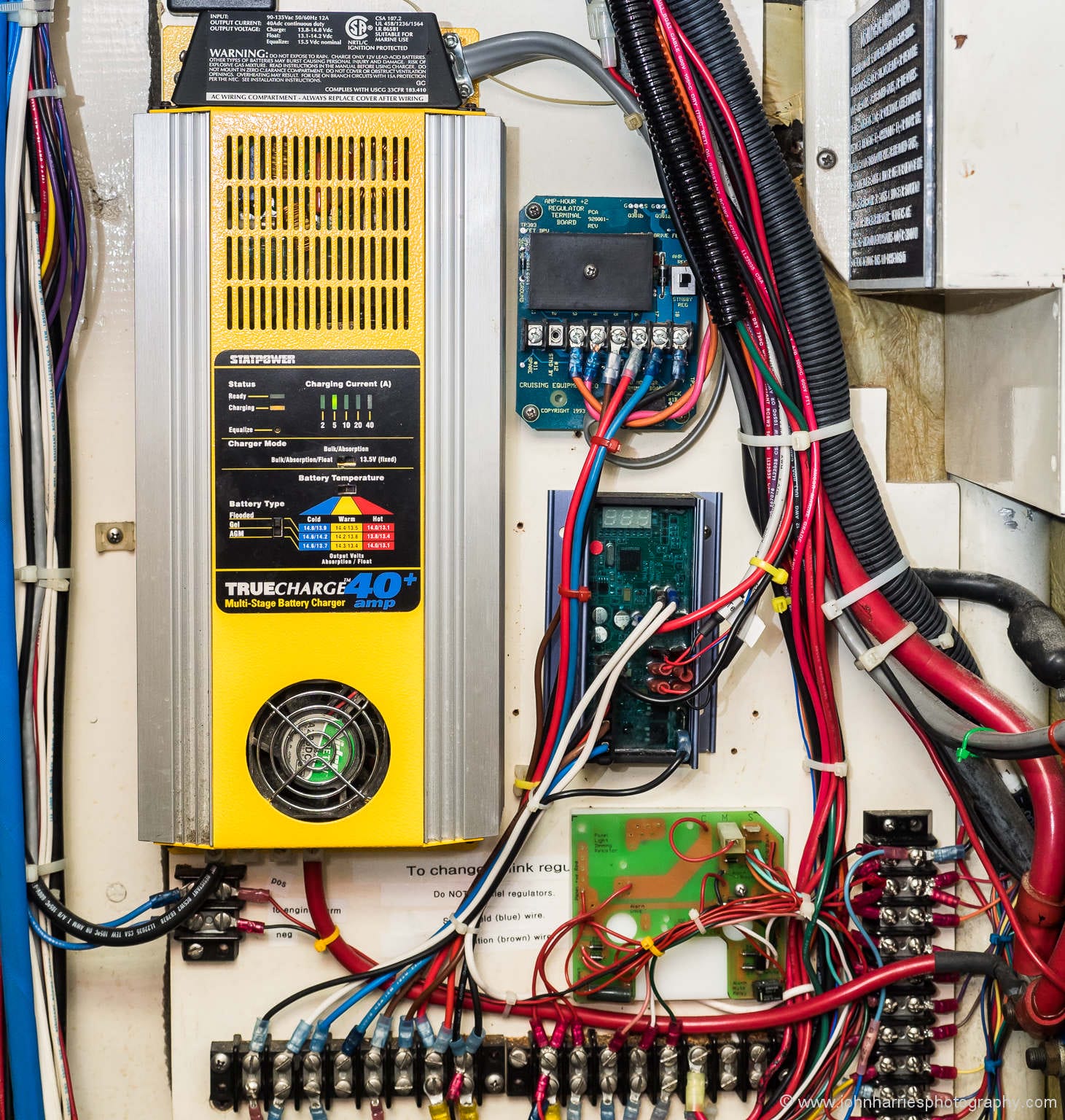
Reading this and the previous articles has gotten me thinking about how complicated electrical systems should be (sorry for being slightly off topic). Looking at what I can see of your setup from the pictures, it appears that you have a robust system that is designed to have multiple charging sources and good redundancy. For the type of cruising you do, I would consider this to be an appropriate level of complication.
I have seen many electrical systems that are far more complicated and harder to troubleshoot on boats that should be far simpler than yours. Ours is significantly simpler but we don’t have several items like a generator. I believe that part of this is a sort of “over-engineering” that can occur when people try to deal with all theoretical eventualities. In my experience, this is especially true of people who buy a boat without a lot of previous experience and then proceed to set about refitting it to be the best bluewater cruiser ever without having ever cruised that boat before. To avoid this, I would recommend doing a sort of fault tree type analysis of your system and seeing what actually adds value and what is a belt and suspenders where the suspenders don’t work without the belt.
When we bought our current boat, I redid the critical parts of the electrical system and nothing else and we cruised it coastal for a year before I did any real work. What the plan for the electrical system looked like at the beginning of that year and the end of that season were totally different as I adjusted what I thought was appropriate and how we would use our boat. In the end, we have a much simpler system than I had originally planned on that is more robust. For example, we eliminated our shorepower setup completely as we realized that we would never use it once the solar was installed since the only time we could plug in was when we are hauled out and the solar covered that. On our first boat, we made a lot of changes (not just electrical) before the first year and ended up finding that many of them were not optimal because we didn’t really understand the boat and us yet.
Eric
Hi Eric,
Great comment full of good points. I’m 100% in agreement with you on the dangers of building the “perfect system” particularly when being done by those new to the boat and voyaging.
Like you, when we bought MC we sailed her for a year and then made changes and almost all of those changes of all systems were simplifications. For example, when we bought her she had two alternators and a refer compressor on the front of the engine. What a dogs breakfast that was! We cut that down to one large alternator.
As to a fault tree analysis of our system, that’s an interesting idea, and a great way to think about it. I guess I have thought it through that way, but not formally. Let me noodle around with it.
Eric, I find myself in the very same predicament as you did before dropping loads of money into upgrading your electrical system. We are getting ready to set sail this fall and i was wondering if you could give me a few more details on what you did. i am looking to hear about what you started out with and then what you ended with.
I have a Beneteau 423 with a 6KW genset, 40A xantrex charger, 150W solar, 80A alternator with about 250AH flooded batteries that are old and need to be replaced. I am going to replace with 2 4D lifeline to give me 400AH. Because of this change i need to upgrade my charging configuration.
Curious to see what you did before i spend thousands!
Thanks
Hi Chris,
I’m sure Eric’s system is very well thought out.
But just so you are aware, Eric is, at least at the moment, a weekend sailor, with occasional multi-week summer cruises. That’s a very different usage profile than than going cruising full time. Also, you have a generator, and he doesn’t. Again a huge difference.
The point being that each of us needs to design a system based on our own usage profile and energy needs, not just copy someone else.
I would suggest reading right through this online book, and them sitting down and clearly writing down what your needs and goals are, including a detailed energy budget, both when at sea and at anchor.
Hi Chris,
John is correct on both accounts, how we currently use our boat and how applicable our system may be to you. To take our system offshore, we would need to increase the generation capabilities but otherwise it would be fine. My comment was more based upon my experience sailing a wide range of boats both for work and fun, both coastal and offshore, and seeing an amazing range of electrical systems. Some systems started more complex than necessary (trying to deal with every eventuality) while others got modified in strange ways over the years, very few of them were as simple as they should have been. I always try to remember that the happiest people in any given anchorage are often on the simplest boat, while they may have to do things more manually, their reliability is really high.
My best suggestion would be to start as John suggests with the energy budget. Then, if it were me, I would create a schematic of the electrical system I would design if starting from scratch, then create a second one of what is currently there. By comparing these 2 schematics, you can figure out how to modify your existing system to do everything it needs to but have a minimum of extra complication. How you handle fault tolerance is another thing you will need to decide although the best way to start is always to not have something that could have a fault.
Good luck.
Eric
Hi Chris,
A couple of thoughts that may help:
First, 400AH seems quite small for full time cruising. Keep in mind that since you will generally only be able to cycle the bank between 50% and about 80% that equates to only ~120 AH usable. If your boat is very simple, that might be enough, particularly since you have solar, but if you have even refrigeration, never mind a freezer or a watermaker, it almost certainly won’t be. The other big consumer to think about is an autopilot. Most of them will burn through 120 AH in less than 24 hours so add in nav lights, navigation equipment etc, and I’m guessing that you would be running the generator every 12 hours at sea. Of course if you have a vane gear, thinks might be a lot better.
And finally, you have a generator, but at the moment your charger is too small to take advantage of it, so you will be running the generator 3 times longer than really needed and worse still the generator will be underloaded. So you will also need at least 100 amps of charging capability. (All this assuming it’s an AC generator, disregard if DC.)
A comment and a question:
I think solar panels can curtail their output without a resistor. The charge controller may open circuit them because they don’t seem to mind being in the sun with their terminals disconnected, but I’m not sure what’s going on inside them.
I have a four battery system that is charged in series by solar panels and a battery monitor with a shunt. That seemed to work well until I added a dual pro AC charger that charges each battery individually. The battery monitor can’t see this and can’t be wired so that it could. I think I’ll have to manually sync the monitor to 100% state of charge whenever I use the AC charger because it doesn’t see those amps going into the batteries. Other ideas? That wouldn’t be so bad, but today I saw overvoltage, so I’ll have to figure that out.
Hi Damon,
Yes, as I understand it, some regulators simply go open circuit when they think the battery is full, but even these will need a way to dissipate current (amps) when charging a battery that has reached it’s acceptance voltage at the amps the panels are supplying. Once again ohms law explains: voltage stays at acceptance (~14.4), resistance increases with charge, therefore amps going into the battery must be reduced from what the panel is outputting. If the regulator simply switched off when the voltage reached acceptance the battery would never get fully charged.
Where is the shunt for the battery monitor? In our system we have the shunt in the negative cable and nothing whatsoever between the shunt and the battery negative terminal. Like you, two of our AC chargers are directly connected to the positive terminals of the batteries, but that doesn’t mater since the negative cables to the charger are connected on the far side of the shunt from the battery. Result: the charge controller reads all amps in and out of the battery.
As I understand “charges each battery individually” I believe the chargers feed wires go directly to the battery terminals, bypassing the common negative, and thus bypassing the shunt. To my understanding this shouldn’t be necessary at all.
However this raises a question in my head – charging batteries separately – doesn’t that increasebank imbalance, requiring extra caution to have the battery bank equalized (esp. in 24V systems with 2x12V in series)?
Thank you two. The solar PV charger has two leads and charges at 48V. The AC charger has eight leads: four sets, 12V each. The shunt, the PV negative, and one of the AC negatives are at the system negative, let’s say 0V. The shunt is installed like yours, except for the AC charger. The other AC negatives are at 12V, 24V, and 36V, which is why I don’t think they can go through the shunt.
I thought the AC charger would correct any imbalance the batteries got being charged in series. Because in series I thought difference in internal resistance would mean they get different amounts of charging.
Hi Damon,
Let’s back up a bit. What is the voltage of your bank 12, 24, or 48 volts? And exactly what is the bank made up of.
There is no reason not to move the negative leads of the charger to the far side shunt from the battery.
Also I don’t think there is much worry about unbalancing batteries that are charged in series. After all by definition they must receive the same amount of amps.
In fact, as I understand it, imbalance is a more of a potential problem with batteries in parallel. Having said that, as long as the batteries are from the same manufacturer and are the same age, in my experience the whole imbalance thing is a non-issue.
Hi John, I have four Concorde SunXtender 1080T group 31 AGM batteries wired in series to provide 48V to the electric motor. The shunt is on the negative of the side of this battery series. I have a DC/DC converter that provides 12V for the rest of the boat’s systems. A Midnite KID charger controller provides solar charging to the system and was the sole means of charging for a few years. Now that the mooring I used to rent was removed to expand the docks, I have a slip and so added an Dual Pro SS4 AC charger to take advantage of the electrical service on the dock I am paying for. Maybe I should have gotten a 48V AC charger. This charger has four sets of 12V leads (it is really four chargers in one case). The reason I don’t think I can put all the negatives where the shunt is, is because the batteries are wired together in series, so the negative of the second battery from the negative terminal is 12V higher than the negative of the first battery, and so on up the series. The AC charger doesn’t care which 12V potential it is filling, so when connected to the battery terminals it charges them all: 0-12, 12-24, 24-36, and 36-48. However, if I moved the negatives to the system negative the AC charger would see 12, 24, 36, and 48 Volt differences because of the series wiring. I had a friend with an electric boat that motored in series and charged in parallel with complex switches that dealt with an issue similar to this, because if I removed the wires that connect the batteries in series when charging with the AC charger, putting the negatives all through the shunt would work.
Hi Damon,
Great, thanks for the details. You are right, with that setup you can’t just place the neg leads from the charger on the far side of the shunt from the batteries. Rather you would need four shunts, as Ernest said.
To my way of thinking, you have too much complexity here. If it were me I would go with a simple 48 volt charger and be done with it.
Ah. If I understand you correctly you have an 48V bank comprised of 4 12V units. And you have 4 chargers charging each unit seperately, right?
John, do you have an idea how this could be solved? Having a shunt on each unit negative, and somehow summing the current up (how the heck could this be done…) ?
Yes that is right. Neat idea with four shunts! I think I will relegate the AC charger to backup as it was meant to be and reset the monitor when the AC charger finishes. A perfect solution isn’t necessary for me and my lake boat, but I threw it out there as a system that doesn’t easily conform the concepts in the post. And as you may have guessed, the boat has an electric motor, so you can add 48v charging challenges as another knock on electric propulsion.
John, one error or omission – a battery is fully charged ONLY when the current is 0.5% of the Ah Capacity – AT THE ABSORPTION VOLTAGE OF 14.4v.
The trouble is you never see this voltage and current combination because the charger will have dropped to FLOAT, at a much lower voltage, well before the battery is fully charged.
To see the charging current at 14.4v the charger will have to be forced back into Absorption Mode by completely turning it off and back on which will raise it back up to 14.4v. When it has stabilised check again to see what the charge current is. It will be very much higher. My Victron charger switches to FLOAT at only 85% full and the current into my LIFELINES drops from 60 amps to 15 amps at 13.2v!!!
Hi Matt,
That’s right…with stupid regulators. But that does not change the fact that a battery is only fully charged when the criteria I specify is met. That’s a simple fact.
The bottom line is that stupid regulators wreck batteries. As to never seeing that voltage, you will if you follow the recommendations in this online book, although that may require getting rid of a charger that has a regulator that can’t be re-programmed to do it’s job properly.
I started the book, and continue it, to expose and fix just this problem: many charger/regulator manufacture units that simply don’t charge batteries fully and that kills batteries and costs us all a lot of money.
The only error or omission here is on the part of companies that make charging devices with poorly designed regulators and then sell them to the unsuspecting.
Thanks John – but I really don’t understand your comments!
“…that does not change the fact that a battery is only fully charged when the criteria I specify is met”…
All regulators are stupid – with very very few exceptions – so how do YOU guarantee full charge? You really don’t make it clear.
If you programme the charger to stay at 14.4v for say 10 hours to GUARANTEE the charge current reduces to 0.5% of Ah Capacity then surely that is over-cooking the batteries at the gassing voltage? Too long at this voltage causes excessive gassing – not good for sealed batteries – but then I agree they shouldn’t be on a cruising boat if they can’t be EQ’d. Most battery manufacturers specify 14.4v or higher up to a charge current of 2% of the Ah Capacity, and THEN to finish in FLOAT. This may take another 12 hours or more as battery acceptance falls.
I hope I’m not being pedantic – but 0.5% of Ah capacity isn’t fully charged at FLOAT voltages. That has to be be made absolutely clear.
There is than a whole new Online Book on what is “100% fully charged”, and why this must be reached very 3-4 weeks to avoid sulfation – if not the batteries MUST be Equalised.
Hi Matt,
You are only reading one chapter of this online book. If you read the other chapters you will find the answers. They key point in this chapter and the last is that it’s the battery that governs when it is fully charged, not the charging sources.
Hi Matt,
I should add to my last comment that a shore power charger that is dropping to float before the batteries are fully charged is less of a problem than say an alternator regulator that does the same thing. In the first case shore power is usually available for long periods so the battery will eventually reach full charge, even at float voltage, albeit with more risk of sulphation, on the other hand, the later case is a much bigger problem since engine run time is limited by many factors and therefore premature dropping to float results in chronically undercharged batteries and failure from sulphation.
At first, it was not really easy to measure amps flowing over the various wires in my boats. Out of solar panel regulator, out of alternator, out of batteries…
Adding shunt and gauge to measure this is very costly.
I purchased a 100$ volt / amp meter with a clamp so that it can be used to measure amps simply by clamping around the wire. This is using induced current in the clamp loop to measure the actual current running in the measured wire. Best tool I ever bought for electrical measurement.
Since then, I have learned a lot around my electrical circuits and devices. This allows me building some reference numbers, and can figure out much more what is going on. Here are 3 examples:
-Alternator for instance, rated 80 amps can nearly deliver 50 amps with a 50% discharged batteries.
-Fridge compressor was supposed to be 2 speed, high with alternator on when sensing high voltage (14.4v), or low while on batteries only (sensing 12.8v or less). It actually draw 4.5 amps, what ever the situation is.
-There is 1 feet long cable, gauge 8 AWG taking all the return from the service battery bank, sometime 50 amps…
Getting all that info is helping me planning for the next move.
Regarding the alternator you should feel lucky – your alternator is sitting half idle and will never complain or overheat and cook itself. Probably thanks to your regulator.
Hi Phil,
That’s a great tip, thanks. Even if one decides to buy a battery monitor with shunt, a good quality clamp on meter is an invaluable tool.
A company called Mastech makes a decent one for about $60 Canadian, for those who weren’t left a Fluke in a relative’s will.
Note: when buying a clamp on amp meter, make sure that it can measure AC and DC current. Many, especially the cheaper on can measure AC and DC voltage but only AC current. Not much use on a sailboat…
Hi Daniel,
Great tip that could save someone a disappointment, thanks.
I dont know if it the right post for it, but do you know this product:
http://www.pbase.com/mainecruising/smart_gauge
An interesting conversation on the same subject :
http://forums.sailboatowners.com/index.php?threads/the-new-balmar-smart-gauge.160510/
Thank you!
Hi Philipe,
Yes, I’m aware of the smart gauge and have read the compass marine analysis, which is, like all his stuff, excellent and complete. By coincidence, our venerable Link 2000 has just bit the big one, so I will be looking at a replacement. That said, I don’t think it will be a Smart Gauge, or at least not alone, since I like to be able to read amps in and out of the battery in real time, which the Smart Gauge can’t do (requires a shunt). I would also need two Smart Gauges since we have two house banks. (Yes, I know that the Smart Gauge has a second battery capacity, but that is limited to voltage reading, with no capacity measurement.)
That said, I think that the Smart Gauge makes a lot of sense, particularly for those without the technical knowledge, or desire, to keep an amp counter properly calibrated.
Hi John
Last week I did a stupid thing and left my engine room lights on (not LED then, are now!) then 2nd error forgot to isolate batteries, came back after 2 days to realize but too late my domestic bank (new in 2015) was down to 8 volts measured on my balmar smart gauge.
I have now charged fully but have noticed they do not hold their charge overnight with fridge loads etc as they did before. Have I completely done them over? or is there any hope?
The bank is 4no 140 amp lead acid truck type batteries.
Thanks for any help you can give
Danny
Hi Danny,
A single mistake like that should not be fatal.
First you need to absolutely sure that you are in fact fully charging them to 100%. See https://www.morganscloud.com/2011/02/10/eleven-steps-to-better-battery-life/ (Tip #11).
Second, it would be a good idea to equalize them as soon as possible: https://www.morganscloud.com/2010/10/05/equalizing-batteries-the-reality/
All that said, if they really are just “truck type starter batteries” and not built to be deep cycled, they may indeed be toast. One comfort, that may not be than big a tragedy since any cruising boat needs to be fitted with deep cycle batters anyway.
Hi John
Thanks for the swift reply and thanks for the extra info links,
Danny
John,
Forgive me for my sycophantic comment – as I’ve said previously, your website is providing so much of the info needed to turn a great old cruiser (1986 Pedrick ‘41) into a successful long-distance traveler. I’ve bought and read Chen/Cheseau’s book on route design; now I’m getting through your book on battery charging. As an engineer, we’re trained to truly understand a subject (the difference between an A and a C in school) so my approach to this boat is to understand all aspects that are within my reach – from heavy wx drogues to propeller/engine/transmission match to energy management. Your work is walking me through much of this, helping to keep my family safe and the sailing successful. For what it’s worth, you are making a difference to this small family preparing to launch from Bayfield, Wisconsin. If we ever meet, the first round is on me.
Chris Hartnett
Minneapolis
s/v Morning Winds
Hi Chris,
What a loverly comment, thank you. Makes it all worth while.
I am currently in the process of upgrading my battery system and there are simply too many options for configurations. Here is where I am. I am looking to update 235Ah Flooded batteries with 400Ah Lifeline bank. My alternator is the stock 80A yanmar and I have a 40A Xantrex charger. I am getting ready to move aboard my boat for the next 3-4 years with my family. The update to the alternator, charger, and battery bank will run me about $4K. By the Way I also have a 6Kw Genset. Here is what I am thinking:
100A Mastervolt Charger
120A Balmar alternator with belt kit and regulator
2 x 200AH Lifeline AGMs.
As I read your post I keep asking myself do I need all of this. What is the minimum viable solution for cruising. Do I upgrade the bank and alternator and keep the 40A charger? Is there another configuration? Any advice would be great.
Thanks,
Hi Chris,
This is a huge subject and there are a lot of variables and so I can’t be precise in answering. The only really right way to size an electrical system is to do a complete energy budget with detailed estimates of usage and charging. (I need to write a chapter on doing that.) Also you don’t say where you will be cruising and whether you will install wind or solar charging.
That said, the system you propose is by no means overkill for cruisers today that tend to have far higher energy needs than we once did.
In fact a 400AH house bank may not be adequate, particularly if you have an evaporator based refrigeration system—they run intermittently all day—or plan to use an autopilot at sea.
One thing I can say for sure: don’t forgo the larger charger since doing so will over double you generator run time to charge your batteries. One idea would be to buy two more 40A Xantrex chargers and parallel them up with the existing one for 120 amps. (This is exactly what we have and it works great as well as giving us backup.)
Also, I would think about taking the alternator up at least one size too > 150 amps. See this chapter for more on that: https://www.morganscloud.com/2013/11/06/10-tips-to-buy-and-install-a-liveaboards-alternator/
In summary, I think that it’s unlikely that the system you are proposing is too big, and in fact the truth may be the opposite. Sorry, I know that’s not good news, but the fact is that having to upsize their electrical system is probably the most common problem new live aboard cruisers face, so better, and probably cheaper in the long run, to get it right now.
Hello John
It has been pleasure to read all your stuff on electrical, batteries and charging. I all ready did have Lifeline / Optima batteries installed by previous quality conscious owner and they lasted for almost 15 years ( Lifeline confirmed serial number). The house batteries consist of 2 groups controlled by a “ 1-2-both” switch always positioned in “ both”
The old huge Xantrex charger and Link 2000 did however leave for another electronic world and I have invested in Victron Charger/ inverter and Victron 700/712 battery monitors
I believe that you also have had Link 2000 and now use Victron , so this is where I really need advise.
The old Link 2000 had a double shunt, “ U “ formed with common ground ( -) and the 2 load sides connecting to load from the 2 house battery groups. The shunts provided by Victron is 2 single 500 amp. I cannot figure out how to connect these new shunts to get a accurate reading for battery monitoring.
The Victron shunts has RJ11 cable connections ,- could I just strip the wires and connect the old shunts to the 2 new Victron 700 series?
Or could I make a “ U / V “ form out of the Victron shunts and then connect to to the 2 Victron 700?
Or put in other way how do you get 2 Victron 700 to work together with 2 house battery groups with “ 1-2-both” setup??
Also changing the 100amp Balmer alternator to a 160amp Balmer , now with Serpentine belt and MaxCharge 614. Can you connect temperature monitoring on both house groups without confusing MaxCharge ?
I am aware that this is a very specific subject but I could imagine that others have 2 groups and would like to monitor.
Thanks for any help
Berst regards
Klaus
iSea / J-46
Hi Kluas,
On no account would I use the old Link shunt. So you need to wire the new shunts in the negative cables between the batteries and the negative common buss bar making sure that there are no loads connected directly to the battery that won’t go through the shunts.
As to the temp sensor on the 614, as I remember it supports two sensors, but if not just put it on one battery and you should be fine since you always keep the switch at both.
Thanks for a well-written and helpful piece. Although I consider myself reasonably intelligent, I still feel a bit (OK, a lot) unsure about all the electrical stuff. Can you recommend a book that would be a good introduction to marine electrical? Thanks
Hi Blake,
Since I have electrical training, I really have not read many books on the subject. I did find this list, which may help. https://www.bluesea.com/support/reference/536/Recommended_Books_on_Marine_Electrical_Systems
Also, I have found anything by Nigel Calder to be good.
Anyone else have a recommendation?
John, I’ve been reading your books on electrical systems along with the many comments as I think I may need to make some changes to my system (4 6V Trojan T-105s in a 12V configuration, about 450 AH total, 100 A alternator and 200 W solar). Coastal cruising primarily, but I am finding that I need to run the engine way more than I would like (2+ hours a day) .
My first question relates to solar – you talk about 200 W of output going into the battery resulting in 16.67 A. The spec on my panels says that output voltage is 17.5 V and so the maximum current output is around 11 A. I asked a manufacturer’s rep how that would relate to charging a 12 V system and he said you just look at the current (11 A) and how long the charging time is. This would imply quite a bit less going into the battery than 200 W I think. It does not make sense to me and perhaps this rep isn’t really all that knowledgeable. I would be interested in your opinion.
My second question relates to alternator output (and if you address this somewhere else, I apologize and please direct me there). I rarely get more than 60 A output from my 100 A alternator – I realize this could be a regulator issue, but couldn’t it also be related to the RPM of the alternator, which is determined by the pulley configuration? Since the engine will run over a wide range of RPM that has to be a factor in the design of the charging system I would think, but I’ve never seen any discussion of that.
Appreciate your thoughts as always.
Bob Andrew
Hi Bob,
First off, 200 watts is indeed 16 amps at 12 volts (200/12=16.666). At the acceptance on your battery, about 14.4 volts that drops to 13.88 (200/14.4=13.88). However, with solar things get more complicated, because solar panels have different voltages than the ideal battery charging voltages.
If you have a cheap and simple voltage regulator it gets around this problem by simply throwing away a bit of the 200 watts. So, in that way, the rep is right.
But this is fixable: To get the full yield from the panel you need a Maximum Power Point Tracking (MPPT) solar controller, which, instead of throwing away some of those watts, steps the voltage down and the amps up thereby using the full watts that the panel is producing.
Of course, in the real world you will not often get a full 200 watts because there are some small losses in the controller as well as drops in efficiency from panel heating, but still a MPPT controller will make quite a difference.
You can read more here: https://www.victronenergy.com/upload/documents/White-paper-Which-solar-charge-controller-PWM-or-MPPT.pdf
As to why your alternator is not putting out, that’s almost certainly a voltage regulator programming problem, given how much you are running to charge. To check, discharge your batteries to 50%, start charging and wait until it settles at say 60 amps and then increase the throttle say 400 rpm. Wait 2 minutes for things to stabilize. If the amps have not gone up, it’s the regulator and not RPM.
John, thanks for your helpful info as always. I’ve now read much more about the ins and outs of solar chargers and I think the way forward is clear. Regarding the alternator, I have more specs on what the output should be and you are right that it cannot be the RPM (output is indicated to be 35A at engine idle and 90A at 2000 RPM) . I have spoken with the engine reps (Beta Marine) and while they have been very helpful on engine related issues, I am not getting anywhere so far with the alternator/regulator situation. I think it’s a black box to them and all they are telling me is that batteries can’t be charged too quickly, but at 50% capacity and resting voltage of 12V I think I should get close to the maximum alternator output properly regulated, not just 60A (and declining from there after 10-15 minutes running)? So, I may have to look elsewhere to get this right, Looking over your info on this topic and all the comments it seems that Balmar is the only real supplier of the type of regulator that is needed. Are there others that I have missed? In case it would be of any use, here is a link to a pdf on the Beta alternator set up: https://www.dropbox.com/s/d8juzaafwmkkq7b/Beta%20Marine%20Engine%20Wiring%20100-05475%2002%20S5%20HE%20100%20Amp%20%26%20Controller.pdf?dl=0
Thanks as always for your input. Bob Andrew
Hi Robert,
Not surprised that Beta could not help. Very few people, even in the marine industry, actually understand how voltage regulators work, even the ones they sell!
And, yes, the problem is almost certainly the Beta controller. As shown by the behaviour you are seeing, it’s switching into float mode far too early. And since there is no mention of being able to change it’s programming, it needs replacing. I have not done a big search, but I can say that the Balmar works fine and is reprogrammable, so probably your best option. Make sure you get the MC-614 (the programable one). Do note though that you will have exactly the same problem with the Balmar until you reprogram it.
All that said, it is just possible that the alternator is defective, but since you will still need to change regulators to be able to change programs, it’s still worth buying the Balmar. Once you have that installed it will display field current %. And if that is over 90% and the alternator is still not putting out, then the alternator needs replacing too.
In this chapter, you use the term “shunt” but don’t explain what a “Shunt” is or does. You also say it is usually on the negative side?? Could you clear this up for me?
Hi RWalters, there is a good explanation on shunts on wikipedia: https://en.wikipedia.org/wiki/Current_sensing#Shunt_resistors
Basically a shunt is a means to measure current entering or leaving the battery bank to always have a most realistic image of your energy balance.
Technically it is done using a resistor causing a (very small) voltage drop, and using Ohms law you can calculate the amperage (current going in/out) from this. The backside of a shunt is that it uses energy by itself, but normally quite below 1 watt.
Hi RWalters.
A good explanation from Ernest. I should have linked to an explanation. I will fix that.
Hi John, thanks for your guidiance through your webpage. I am beginning to understand this complex subject better. On this point under heading Naming Names, “And started acceptance charging in which both regulators keep the voltage at 14.4 and the amps drop off as the battery’s internal resistance increases.” Now, what determines how much amp is provided by the alternator and solar panels at the acceptance stage? Is there a way to maximize the full charge of the solar panel at this stage?
Hi Ee Kiat,
As I explain in the post, the internal resistance of the battery controls how many amps flow into it one acceptance is reached. That’s the whole point: there is no way to increase the charge rate, other than to increase the voltage over 14.4, and that would damage the battery. All explained by ohms law.
Hi John, sorry my question was not clear. I am not trying to increase the charge rate. Lets try again. At acceptance stage. Both the alternator and solar maintains the voltage at 14.4V. The alternator has an output of 100A and the solar has an output of 16.7A. However the battery only will accept 100A (say, the internal resistance has reached a stage that dictates that). Is there a way that I can have the solar provides 16.7A and the alternator provides 83.3A totalling 100A. That will make the alternator work less and the Solar out maximized for the rest of the charging.
Hi Ee Kiat,
Short answer, no. But why would it matter?